

Question: 1. - The part shown in the Figure has been rough turned. Write a word address program segment using TNR compensation to perform the
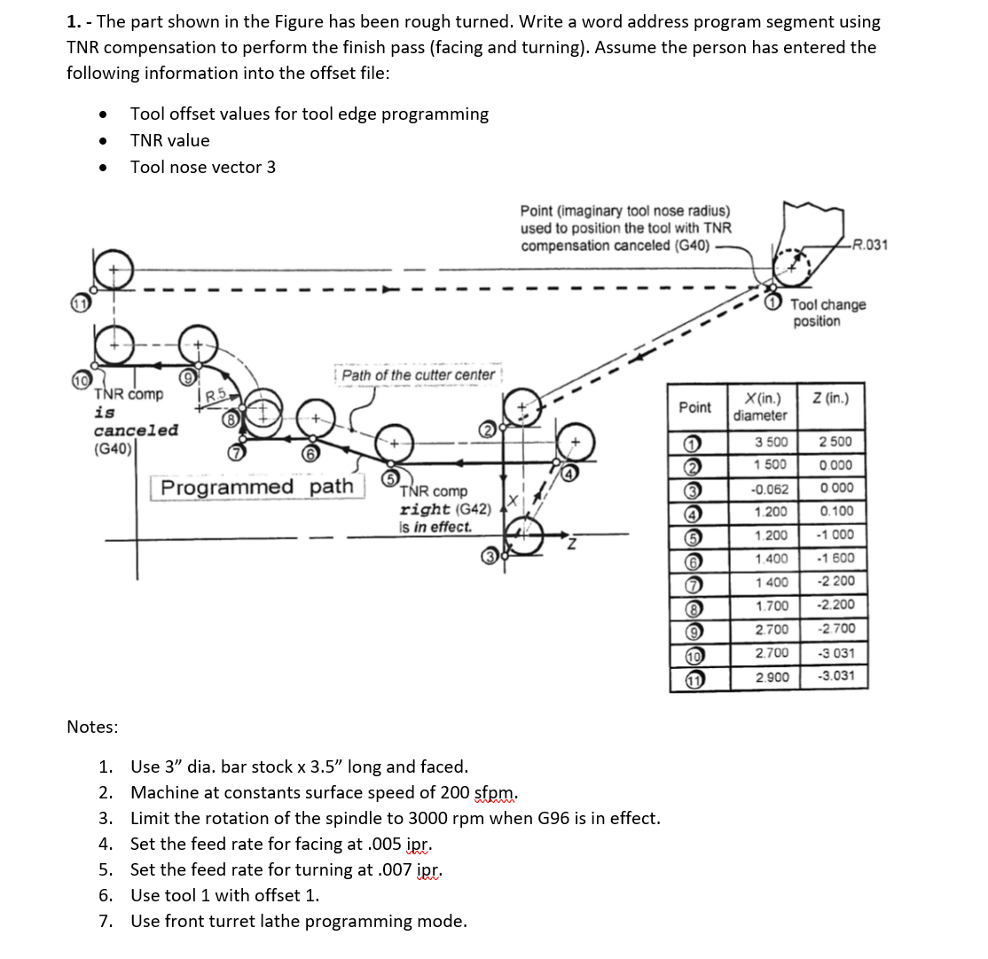
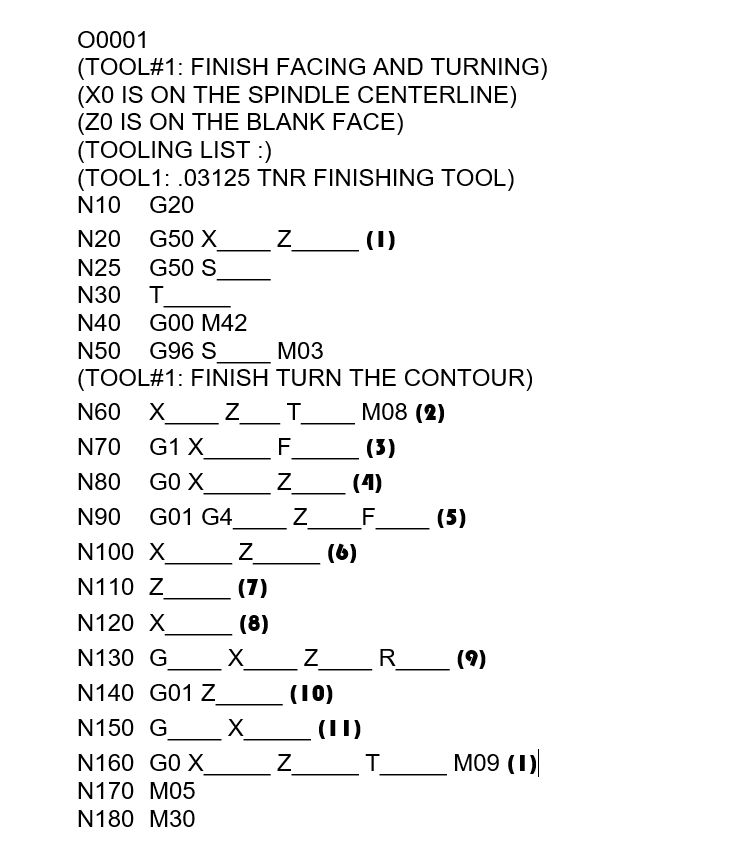
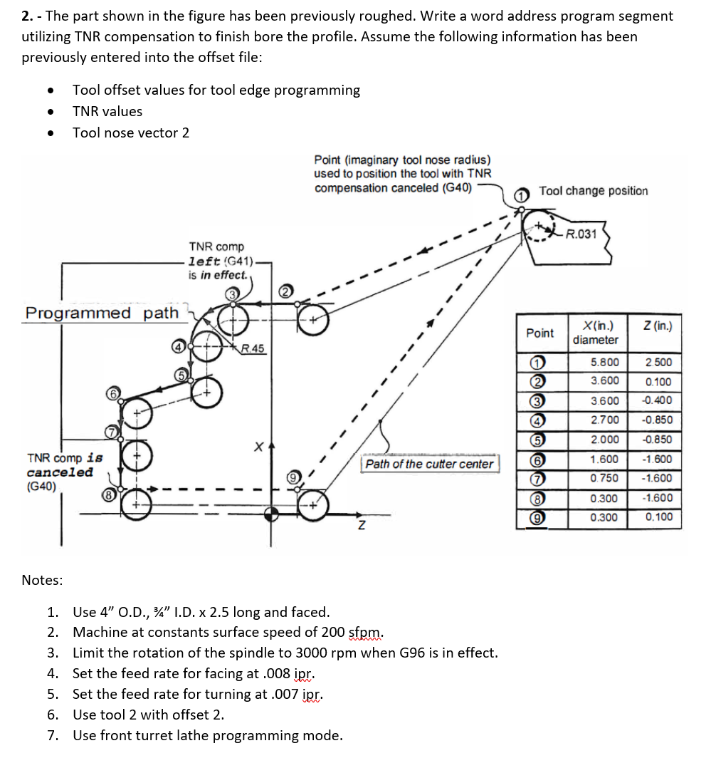
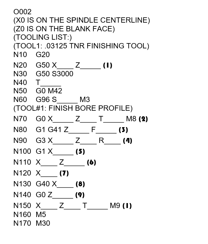
1. - The part shown in the Figure has been rough turned. Write a word address program segment using TNR compensation to perform the finish pass (facing and turning). Assume the person has entered the following information into the offset file: Tool offset values for tool edge programming TNR value Tool nose vector 3 TNR comp is canceled (G40)| Notes: Path of the cutter center Programmed path TNR comp right (G42) is in effect. Point (imaginary tool nose radius) used to position the tool with TNR compensation canceled (G40) 1. Use 3" dia. bar stock x 3.5" long and faced. 2. Machine at constants surface speed of 200 sfpm. 3. Limit the rotation of the spindle to 3000 rpm when G96 is in effect. 4. Set the feed rate for facing at .005 ipr. 5. Set the feed rate for turning at .007 ipr. 6. Use tool 1 with offset 1. 7. Use front turret lathe programming mode. Point 1 2 (3 (4) (65 (6 (7 (8) 9 10 al 11 X(in.) diameter 3 500 1 500 -0.062 1.200 1.200 1.400 1400 1.700 2.700 2.700 2.900 -R.031 Tool change position Z (in.) 2 500 0.000 0.000 0.100 -1.000 -1.600 -2 200 -2.200 -2.700 -3 031 -3.031 00001 (TOOL#1: FINISH FACING AND TURNING) (XO IS ON THE SPINDLE CENTERLINE) (ZO IS ON THE BLANK FACE) (TOOLING LIST :) (TOOL1: .03125 TNR FINISHING TOOL) N10 G20 N20 G50 X Z ________ (1) N25 G50 S N30 T N40 GO0 M42 N50 G96 S M03 (TOOL#1: FINISH TURN THE CONTOUR) N60 X_Z_____T_ M08 (2) N70 G1 X (3) N80 GO X N90 G01 G4 N100 X N110 Z N120 X N130 G _X N140 G01 Z N150 G N160 GO X N170 M05 N180 M30 Z (7) (8) X FLN Z Z (4) _F_________ (5) Z (6) _Z______R__ (10) (II) _T___________ (9) M09 (1) 2.- The part shown in the figure has been previously roughed. Write a word address program segment utilizing TNR compensation to finish bore the profile. Assume the following information has been previously entered into the offset file: Tool offset values for tool edge programming TNR values Tool nose vector 2 Programmed path TNR comp is canceled (G40) Notes: TNR comp left (G41). is in effect. R.45 Point (imaginary tool nose radius) used to position the tool with TNR compensation canceled (G40) Path of the cutter center 1. Use 4" O.D., 34" I.D. x 2.5 long and faced. 2. Machine at constants surface speed of 200 sfpm. 3. Limit the rotation of the spindle to 3000 rpm when G96 is in effect. 4. Set the feed rate for facing at .008 ipr. 5. Set the feed rate for turning at .007 ipr. 6. Use tool 2 with offset 2. 7. Use front turret lathe programming mode. Tool change position Point 1 2 (3) 4 5 6 (7) (8) (9) R.031 X(in.) diameter Z (in.) 5.800 2.500 3.600 0.100 3.600 -0.400 2.700 -0.850 2.000 -0.850 1.600 -1.600 0.750 -1.600 -1.600 0.100 0.300 0.300 0002 (XO IS ON THE SPINDLE CENTERLINE) (ZO IS ON THE BLANK FACE) (TOOLING LIST:) (TOOL1: .03125 TNR FINISHING TOOL) N10 G20 N20 G50 X _ (1) N30 G50 S3000 N40 T N50 GO M42 N60 G96 S M3 (TOOL#1: FINISH BORE PROFILE) Z N70 GO X N80 G1 G41 Z N90 G3 X N100 G1 X N110 X N120 X N130 G40 X N140 GO Z N150 X N160 M5 N170 M30 Z (7) Z Z Z (5) (8) (9) F (6) T T R M8 (2) (3) (4) M9 (1)
Step by Step Solution
There are 3 Steps involved in it

Get step-by-step solutions from verified subject matter experts