

Question: 1 . ?Which random / systematic sources of error were present in the experiment? How did they affect your results? 2 . ?Which segments of
?Which randomsystematic sources of error were present in the experiment? How did they affect your results?
?Which segments of the circuit loops contributed to the measured magnetic force? Explain mathematically include diagram if necessary
?If you rotate the magnet assembly by deg or switch the polarity of the circuit by exchanging the ve and the ve side of the power supply, how would your observations in part B mass ?slope, intercept, magnetic field ?change?
?Would you be able to measure the Earths magnetic field with your se curve.
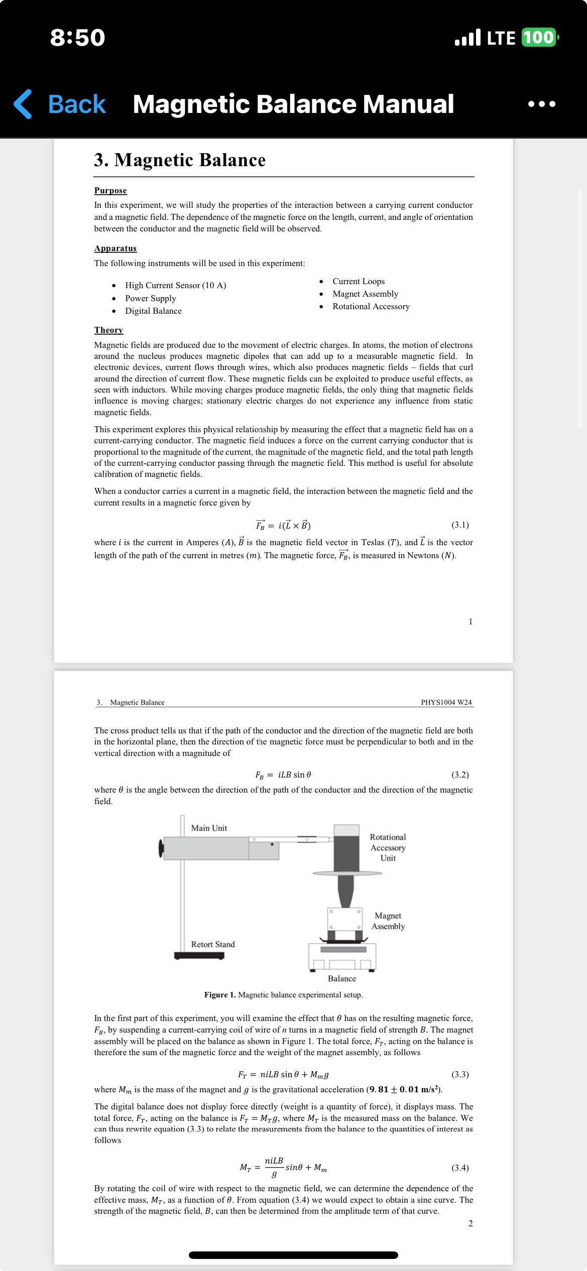
8:50 Back Magnetic Balance Manual 3. Magnetic Balance Purpose . LTE 100 In this experiment, we will study the properties of the interaction between a carrying current conductor and a magnetic field. The dependence of the magnetic force on the length, current, and angle of orientation between the conductor and the magnetic field will be observed. Apparatus The following instruments will be used in this experiment: High Current Sensor (10 A) Power Supply Digital Balance Current Loops Magnet Assembly Rotational Accessory Theory Magnetic fields are produced due to the movement of electric charges. In atoms, the motion of electrons around the nucleus produces magnetic dipoles that can add up to a measurable magnetic field. In electronic devices, current flows through wires, which also produces magnetic fields - fields that curl around the direction of current flow. These magnetic fields can be exploited to produce useful effects, as seen with inductors. While moving charges produce magnetic fields, the only thing that magnetic fields influence is moving charges; stationary electric charges do not experience any influence from static magnetic fields. This experiment explores this physical relationship by measuring the effect that a magnetic field has on a current-carrying conductor. The magnetic field induces a force on the current carrying conductor that is proportional to the magnitude of the current, the magnitude of the magnetic field, and the total path length of the current-carrying conductor passing through the magnetic field. This method is useful for absolute calibration of magnetic fields. When a conductor carries a current in a magnetic field, the interaction between the magnetic field and the current results in a magnetic force given by FB = i(L B) (3.1) where i is the current in Amperes (A), B is the magnetic field vector in Teslas (T), and I is the vector length of the path of the current in metres (m). The magnetic force, FB, is measured in Newtons (N). 1 3. Magnetic Balance PHYS1004 W24 The cross product tells us that if the path of the conductor and the direction of the magnetic field are both in the horizontal plane, then the direction of the magnetic force must be perpendicular to both and in the vertical direction with a magnitude of FB = iLB sin 0 (3.2) where is the angle between the direction of the path of the conductor and the direction of the magnetic field. Main Unit Retort Stand Balance Rotational Accessory Unit Magnet Assembly Figure 1. Magnetic balance experimental setup. In the first part of this experiment, you will examine the effect that 0 has on the resulting magnetic force, FB, by suspending a current-carrying coil of wire of n turns in a magnetic field of strength B. The magnet assembly will be placed on the balance as shown in Figure 1. The total force, Fr, acting on the balance is therefore the sum of the magnetic force and the weight of the magnet assembly, as follows FT niLB sin 0 + Mmg (3.3) where Mm is the mass of the magnet and g is the gravitational acceleration (9.81 0.01 m/s). The digital balance does not display force directly (weight is a quantity of force), it displays mass. The total force, Fr, acting on the balance is F = Mg, where MT is the measured mass on the balance. We can thus rewrite equation (3.3) to relate the measurements from the balance to the quantities of interest as follows niLB MT = g -sino + Mm (3.4) By rotating the coil of wire with respect to the magnetic field, we can determine the dependence of the effective mass, MT, as a function of 0. From equation (3.4) we would expect to obtain a sine curve. The strength of the magnetic field, B, can then be determined from the amplitude term of that curve. 2
Step by Step Solution
There are 3 Steps involved in it

Get step-by-step solutions from verified subject matter experts