

Question: 11. i). Generate the Boolean expression that describes output D in the figure below D=_______________________________________________ ii. Re-draw the combinational logic circuit given above in Circuitlab.
11. i). Generate the Boolean expression that describes output D in the figure below
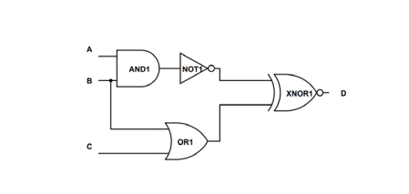
D=_______________________________________________
ii. Re-draw the combinational logic circuit given above in Circuitlab. Connect appropriate DC voltage sources to inputs A, B and C to represent the logic levels A=1 B=0 C=0. 5 Volts should represent an input of 1 whereas 0 V represents a binary input value of 0. Connect a voltmeter to the output of the circuit to display the voltage at output D. Simulate the circuit (run DC solver) and display the voltage value displayed on the voltmeter. Print your circuit clearly showing the voltage obtained on the voltmeter.
AND1 NOT XNOR1 OR1
Step by Step Solution
There are 3 Steps involved in it

Get step-by-step solutions from verified subject matter experts