

Question: 1.2) Read the slides: from # 7 to # 14 and answer the following: What is CCUS? Where is CCUS happening (examples of projects)? How
1.2) Read the slides: from # 7 to # 14 and answer the following: What is CCUS? Where is CCUS happening (examples of projects)? How is CO2 captured? Then, especially concentrate on slides: 13 and 14 (Capture Technologies). Write only the names of those Capture Technologies. 1.3) What is green hydrogen? How is it made? How do we use it? (No further information is asked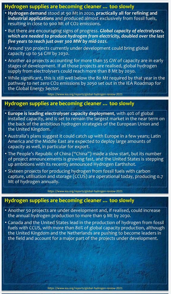
1.4) The IEA (in the reference file given above) states that: Hydrogen supplies are becoming cleaner too slowly. Please read the slides: 24, 25, 26 and give a summary of that statement
PLEASE CHECK THE FILES ABOVE AND ANSWER THE QUESSTION ACCORDING TO THE GIVEN PASSAGES
THANKS ALOTS I PROMISE YOU A THUMB
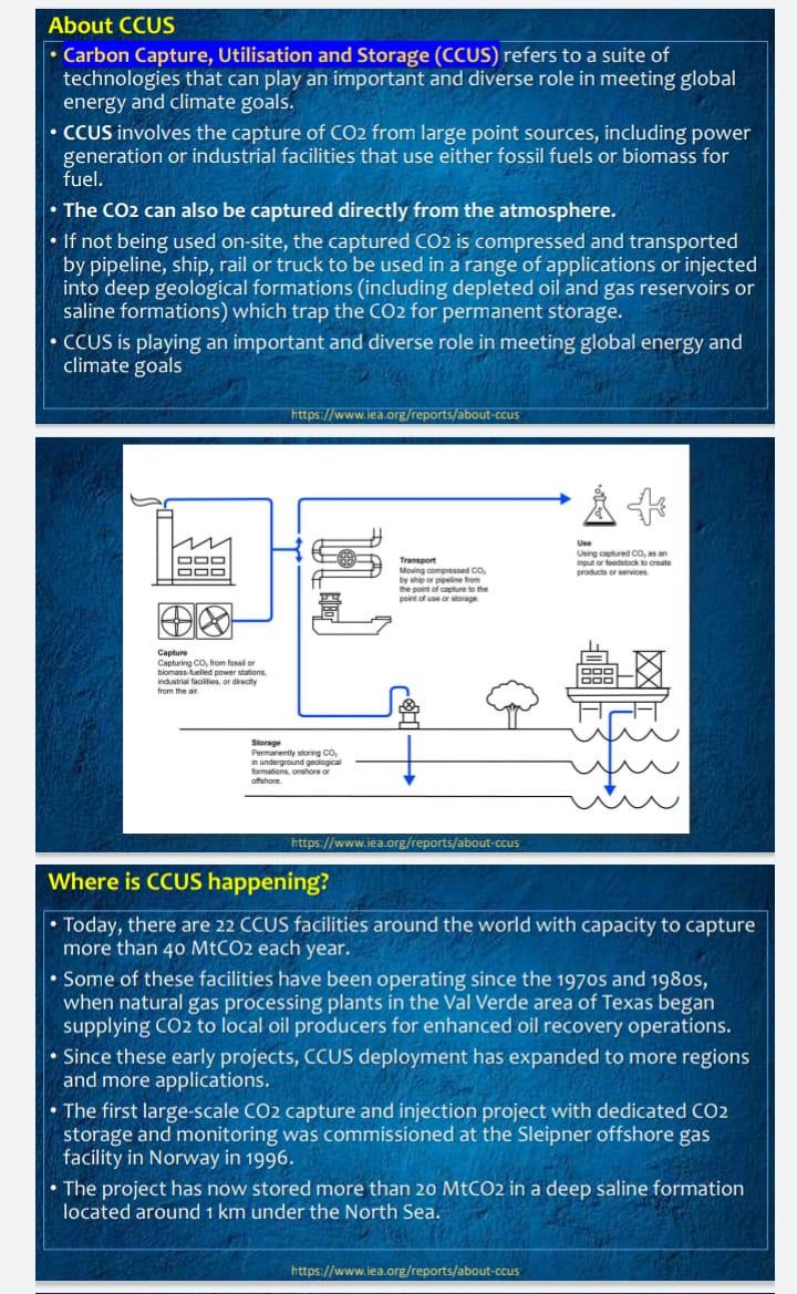
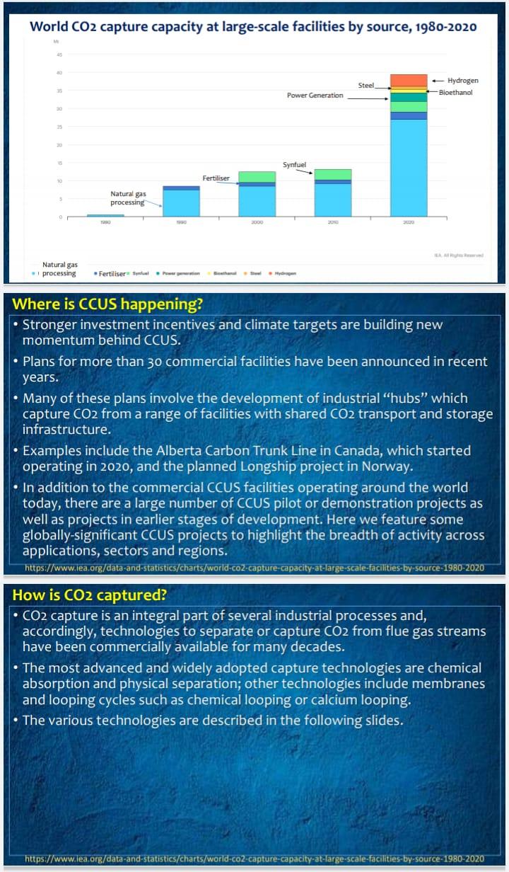
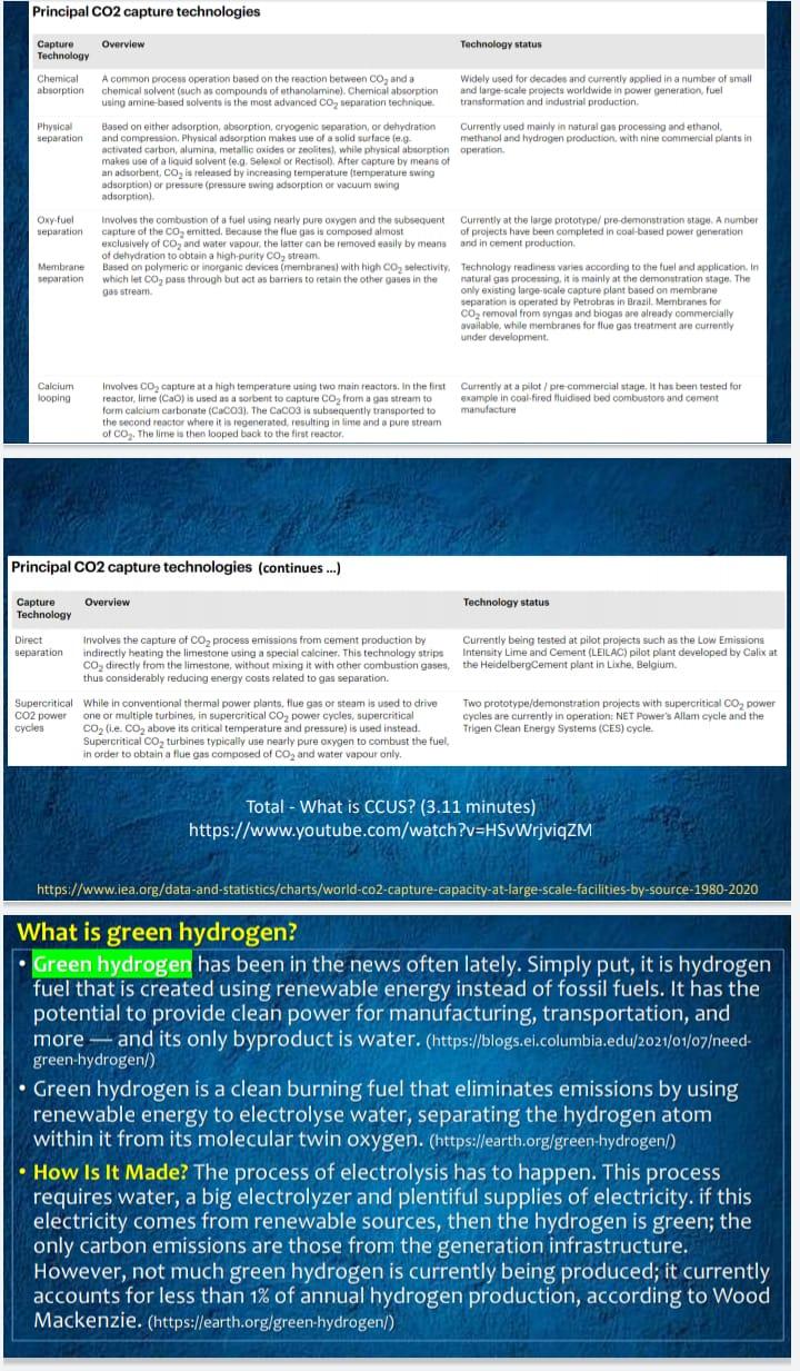
About CCUS Carbon Capture, Utilisation and Storage (CCUS) refers to a suite of technologies that can play an important and diverse role in meeting global energy and climate goals. CCUS involves the capture of CO2 from large point sources, including power generation or industrial facilities that use either fossil fuels or biomass for fuel. The CO2 can also be captured directly from the atmosphere. If not being used on-site, the captured CO2 is compressed and transported by pipeline, ship, rail or truck to be used in a range of applications or injected into deep geological formations (including depleted oil and gas reservoirs or saline formations) which trap the CO2 for permanent storage. CCUS is playing an important and diverse role in meeting global energy and climate goals https://www.iea.org/reports/about-ccus A+ Use Transport 000 000 Using captured CD, asa input or or feedstock to create products or services Moving compressed CO by ship or ppine from the point of capture to th Capture Capturing CO, from for biomass fuelled power stations industrial facilities, or directly from the air Storage Permanently storing CO, in underground geological formations onshore of offshore https://www.iea.org/reports/about-ccus Where is CCUS happening? Today, there are 22 CCUS facilities around the world with capacity to capture more than 40 MtCO2 each year. Some of these facilities have been operating since the 1970s and 1980s, when natural gas processing plants in the Val Verde area of Texas began supplying CO2 to local oil producers for enhanced oil recovery operations. Since these early projects, CCUS deployment has expanded to more regions and more applications. The first large-scale CO2 capture and injection project with dedicated CO2 storage and monitoring was commissioned at the Sleipner offshore gas facility in Norway in 1996. The project has now stored more than 20 MtCO2 in a deep saline formation located around 1 km under the North Sea. https://www.iea.org/reports/about-ccus World CO2 capture capacity at large-scale facilities by source, 1980-2020 Steel - Hydrogen Bioethanol Power Generation 25 Synfuel Fertiliser Natural gas processing 1990 SAA Red Natural gas processing Fertiliser ynfual Power generation Hydrogen Where is CCUS happening? Stronger investment incentives and climate targets are building new momentum behind CCUS. Plans for more than 30 commercial facilities have been announced in recent years. Many of these plans involve the development of industrial "hubs" which capture CO2 from a range of facilities with shared CO2 transport and storage infrastructure. Examples include the Alberta Carbon Trunk Line in Canada, which started operating in 2020, and the planned Longship project in Norway. In addition to the commercial CCUS facilities operating around the world today, there are a large number of CCUS pilot or demonstration projects as well as projects in earlier stages of development. Here we feature some globally-significant CCUS projects to highlight the breadth of activity across applications, sectors and regions. https://www.iea.org/data-and-statistics/charts/world-co2-capture-capacity-at-large-scale-facilities-by-source-1980-2020 How is CO2 captured? CO2 capture is an integral part of several industrial processes and, accordingly, technologies to separate or capture CO2 from flue gas streams have been commercially available for many decades. The most advanced and widely adopted capture technologies are chemical absorption and physical separation; other technologies include membranes and looping cycles such as chemical looping or calcium looping. The various technologies are described in the following slides. https://www.lea.org/data-and-statistics/charts/world-co2-capture-capacity-at-large-scale-facilities-by-source-1980-2020 2000 Principal CO2 capture technologies Overview Technology status Capture Technology Chemical A common process operation based on the reaction between CO and a absorption chemical solvent (such as compounds of ethanolamine). Chemical absorption using amine-based solvents is the most advanced CO separation technique. Widely used for decades and currently applied in a number of small and large-scale projects worldwide in power generation, fuel transformation and industrial production. Physical separation Currently used mainly in natural gas processing and ethanol, methanol and hydrogen production, with nine commercial plants in operation. Based on either adsorption, absorption, cryogenic separation, or dehydration and compression. Physical adsorption makes use of a solid surface (e.g activated carbon, alumina, metallic oxides or zeolites), while physical absorption makes use of a liquid solvent (e.g. Selexol or Rectisol). After capture by means of an adsorbent, CO is released by increasing temperature (temperature swing adsorption) or pressure (pressure swing adsorption or vacuum swing adsorption). Oxy-fuel separation Involves the combustion of a fuel using nearly pure oxygen and the subsequent capture of the CO emitted. Because the flue gas is composed almost exclusively of CO and water vapour, the latter can be removed easily by means of dehydration to obtain a high-purity CO stream. Currently at the large prototype/ pre-demonstration stage. A number of projects have been completed in coal-based power generation and in cement production. Membrane separation Based on polymeric or inorganic devices (membranes) with high CO selectivity, which let CO pass through but act as barriers to retain the other gases in the gas stream. Technology readiness varies according to the fuel and application. In natural gas processing, it is mainly at the demonstration stage. The only existing large-scale capture plant based on membrane separation is operated by Petrobras in Brazil. Membranes for CO removal from syngas and biogas are already commercially available, while membranes for flue gas treatment are currently under development. Calcium looping Involves CO capture at a high temperature using two main reactors. In the first reactor, lime (CaO) is used as a sorbent to capture CO from a gas stream to form calcium carbonate (CaCO3). The CaCO3 is subsequently transported to the second reactor where it is regenerated, resulting in lime and a pure stream. of CO. The lime is then looped back to the first reactor. Currently at a pilot/pre-commercial stage, it has been tested for example in coal-fired fluidised bed combustors and cement manufacture Principal CO2 capture technologies (continues...) Overview Technology status Capture Technology Direct separation Involves the capture of CO process emissions from cement production by indirectly heating the limestone using a special calciner. This technology strips CO directly from the limestone, without mixing it with other combustion gases, thus considerably reducing energy costs related to gas separation. Currently being tested at pilot projects such as the Low Emissions Intensity Lime and Cement (LEILAC) pilot plant developed by Calix at the HeidelbergCement plant in Lixhe, Belgium. Supercritical While in conventional thermal power plants, flue gas or steam is used to drive CO2 power one or multiple turbines, in supercritical CO power cycles, supercritical cycles CO (.e. CO above its critical temperature and pressure) is used instead. Supercritical CO, turbines typically use nearly pure oxygen to combust the fuel, in order to obtain a flue gas composed of CO and water vapour only. Two prototype/demonstration projects with supercritical CO power cycles are currently in operation: NET Power's Allam cycle and the Trigen Clean Energy Systems (CES) cycle. Total - What is CCUS? (3.11 minutes) https://www.youtube.com/watch?v=HSvWrjviqZM https://www.iea.org/data-and-statistics/charts/world-co2-capture-capacity-at-large-scale-facilities-by-source-1980-2020 What is green hydrogen? Green hydrogen has been in the news often lately. Simply put, it is hydrogen fuel that is created using renewable energy instead of fossil fuels. It has the potential to provide clean power for manufacturing, transportation, and more and its only byproduct is water. (https://blogs.ei.columbia.edu/2021/01/07eed- green-hydrogen/) Green hydrogen is a clean burning fuel that eliminates emissions by using renewable energy to electrolyse water, separating the hydrogen atom within it from its molecular twin oxygen. (https://earth.org/green-hydrogen/) How Is It Made? The process of electrolysis has to happen. This process requires water, a big electrolyzer and plentiful supplies of electricity. if this electricity comes from renewable sources, then the hydrogen is green; the only carbon emissions are those from the generation infrastructure. However, not much green hydrogen is currently being produced; it currently accounts for less than 1% of annual hydrogen production, according to Wood Mackenzie. (https://earth.org/green-hydrogen/) Hydrogen supplies are becoming cleaner ... too slowly Hydrogen demand stood at 90 Mt in 2020, practically all for refining and industrial applications and produced almost exclusively from fossil fuels, resulting in close to 900 Mt of CO2 emissions. But there are encouraging signs of progress. Global capacity of electrolysers, which are needed to produce hydrogen from electricity, doubled over the last five years to reach just over 300 MW by mid-2021. Around 350 projects currently under development could bring global capacity up to 54 GW by 2030. Another 40 projects accounting for more than 35 GW of capacity are in early stages of development. If all those projects are realised, global hydrogen supply from electrolysers could reach more than 8 Mt by 2030. While significant, this is still well below the 80 Mt required by that year in the pathway to net zero CO2 emissions by 2050 set out in the IEA Roadmap for the Global Energy Sector. https://www.iea.org/reports/global-hydrogen-review-2021 Hydrogen supplies are becoming cleaner... too slowly Europe is leading electrolyser capacity deployment, with 40% of global installed capacity, and is set to remain the largest market in the near term on the back of the ambitious hydrogen strategies of the European Union and the United Kingdom. Australia's plans suggest it could catch up with Europe in a few years; Latin America and the Middle East are expected to deploy large amounts of capacity as well, in particular for export. The People's Republic of China ("China") made a slow start, but its number of project announcements is growing fast, and the United States is stepping up ambitions with its recently announced Hydrogen Earthshot. Sixteen projects for producing hydrogen from fossil fuels with carbon capture, utilisation and storage (CCUS) are operational today, producing 0.7 Mt of hydrogen annually. https://www.iea.org/reports/global-hydrogen-review-2021 Hydrogen supplies are becoming cleaner... too slowly Another 50 projects are under development and, if realised, could increase the annual hydrogen production to more than 9 Mt by 2030. Canada and the United States lead in the production of hydrogen from fossil fuels with CCUS, with more than 80% of global capacity production, although the United Kingdom and the Netherlands are pushing to become leaders in the field and account for a major part of the projects under development. https://www.iea.org/reports/global-hydrogen-review-2021Step by Step Solution
There are 3 Steps involved in it

Get step-by-step solutions from verified subject matter experts