

Question: +12V 3- Please inspect the given 16F877A assembly code and circuit. I- Inspect the below given code. What this program does (10p)? +5V R1 99
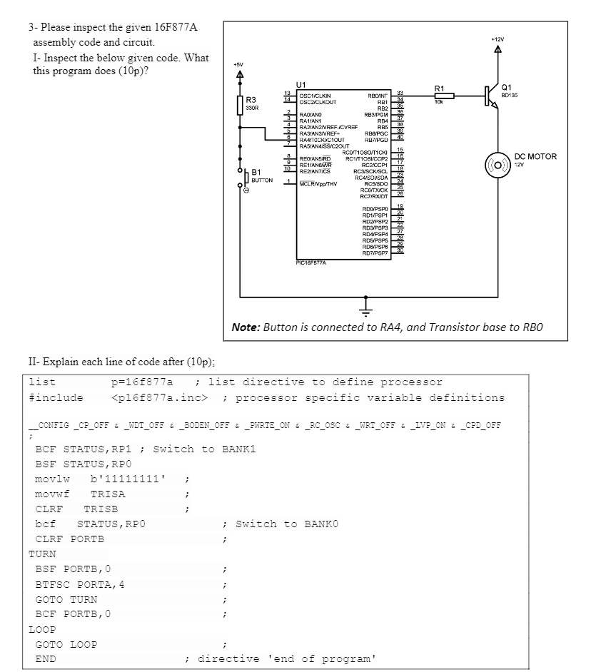
+12V 3- Please inspect the given 16F877A assembly code and circuit. I- Inspect the below given code. What this program does (10p)? +5V R1 99 Q1 BD130 R3 330R 10k U1 13 OSC1/CLKIN 2 RECINT OSC2/CLKOUT RB1 RB2 RAJANO RBPOM RA1/AN1 RB4 RAZIANZ/REF-ICVREF RBS RASVANS/REF RBG/PGC RAUTOCKICIOUT RB PGD RASIANA/SS/C2OUT RCOT10SOT1CKI REOIANORD RC1/T10SUCCP2 RC2CCP1 RE/ANS/WR 10 REJANCS RCSVSCKISCL RCUISDISDA 1 MCLRAPP/THV RC5/SDO | REMT XSK RCZRX/DT 15 16 17 DC MOTOR 12V ODT B1 BUTTON 19 20 RDOPSPO RD1/PSP1 ROOFSP2 RDFSP3 RD4/FSP4 RDS/FSPS RDS/PSPS RD7PSP FIC16F877A Note: Button is connected to RA4, and Transistor base to RBO II- Explain each line of code after (10p): list p=16F877a ; list directive to define processor #include
Step by Step Solution
There are 3 Steps involved in it

Get step-by-step solutions from verified subject matter experts