

Question: (15 pts) When powering real electronics systems (such as microcontrollers or sensors) from batteries, we don't actually connect the battery voltage directly to the Vpp
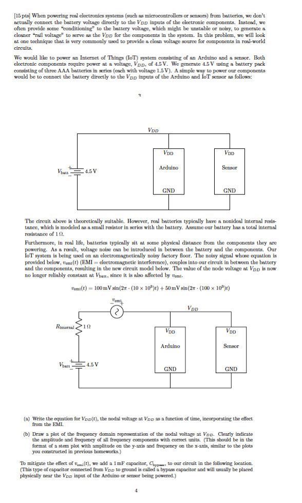
(15 pts) When powering real electronics systems (such as microcontrollers or sensors) from batteries, we don't actually connect the battery voltage directly to the Vpp inputs of the electronic components. Instead, we often provide some "conditioning to the battery voltage, which might be unstable or noisy, to generate a cleaner "rail voltage" to serve as the Vpp for the components in the system. In this problem, we will look at one technique that is very commonly used to provide a clean voltage source for components in real-world circuits. We would like to power an Internet of Things (IoT) system consisting of an Arduino and a sensor. Both electronic components require power at & voltage, Vpp, of 4.5V. We generate 4.5 V using a battery pack consisting of three AAA batteries in series (each with voltage 1.5V). A simple way to power our components would be to connect the battery directly to the Vpp inputs of the Arduino and IoT sensor as follows: VOD VDD Vpp Arduino Sensor -4.5 V GND GND The circuit above is theoretically suitable. However, real batteries typically have a nonideal internal resis tance, which is modeled as a small resistor in series with the battery. Assume our battery has a total internal resistance of 10 Furthermore, in real life, batteries typically sit at some physical distance from the components they are powering. As a result, voltage noise can be introduced in between the battery and the components. Our IoT system is being used on an electromagnetically noisy factory floor. The noisy signal whoso equation is provided below, t'ami(t) (EMI = electromagnetic interference), couples into our circuit in between the battery and the components, resulting in the new circuit model below. The value of the node voltage at Vpp is now no longer reliably constant at Vbatt, since it is also affected by Nomi lem:(t) = 100 mV sin(2x - (10 x 10')) + 50mV sin(2. (100 x 10")) Com Vpp Rinternal 12 VOD VpD Arduino Sensor Vhuu =4.5 V GND GND (a) Write the equation for Vpo(t), the nodal voltage at Vpp as a function of time, incorporating the effect from the EMI (b) Draw a plot of the frequency domain representation of the nodal voltage at Vop. Clearly indicate the amplitude and frequency of all frequency components with correct units. (This should be in the format of a stem plot with amplitude on the y-axis and frequency on the x-axis, similar to the plots you constructed in previous homeworks.) To mitigate the effect of vi(t), we add a 1mF capacitor, Cypto our circuit in the following location. (This type of capacitor connected from Vpp to ground is called a bypass capacitor and will usually be placed physically near the Vpp input of the Arduino or sensor being powered.)
Step by Step Solution
There are 3 Steps involved in it

Get step-by-step solutions from verified subject matter experts