

1.Take the data from Figure 1 and perform an energy balance (First Law) to verify all the...
Question:
- 1.Take the data from Figure 1 and perform an energy balance (First Law) to verify all the mass and energy flowing into and out of the engine nets out to zero. This is a very basic first step in “desk checking” laboratory dynamometer testing. If all of the mass and energy flows net out to zero, then you will have some confidence in the correctness of the lab measurements. Note: in this data, you should expect the energy flow into the engine to be slightly greater than what is observed to be flowing out. This sounds erroneous until you consider that we cannot easily measure some of the heat lost from the engine due to radiation & convection within the dyno cell room itself. Figure 2 shows a suggested diagram to show the control volume and energy balance.
- 2.Calculate the theoretical amount of mass and volumetric air flow for the cooling air flow (fan air flow). Use ambient air for the intake air coming into the CAC, and use a target fan air discharge temperature of 50 degrees C for the air discharged from the cooling package.
- 3.Compute the mass and volumetric flow of the exhaust gas leaving the muffler. Keep in mind the total mass flow is the sum of the fuel + intake air flow. Assume the exhaust gas is at the measured exhaust temperature from the dyno test and at ambient atmospheric air pressure.
- 4.Write an engineering report summarizing your findings, making recommendations, and detailing any analysis you have performed to support your efforts.
- 5.Make a presentation to the appropriate staff to discuss findings and recommendations.
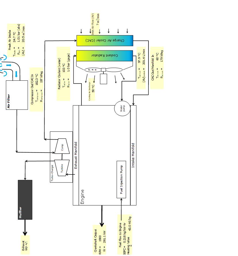
Figure 1:Engine dynamometer test results.
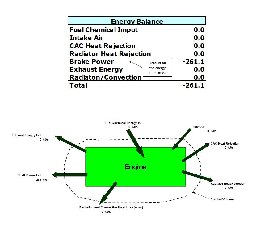
Figure 2, Energy Balance:This shows a proposed format for the energy balance as it applies to the engine. Notice here a term called Radiation/Convection has been added to “force” the energy balance to net out to zero. This is necessary because it is not possible to easily measure this. Typically, we might expect the Radiation/Convection loss to be 5% or less of the fuel energy coming into the engine. Note this should be a negative amount (heat loss). A positive result or values greater than 5% indicate errors in lab measurements or computational errors.
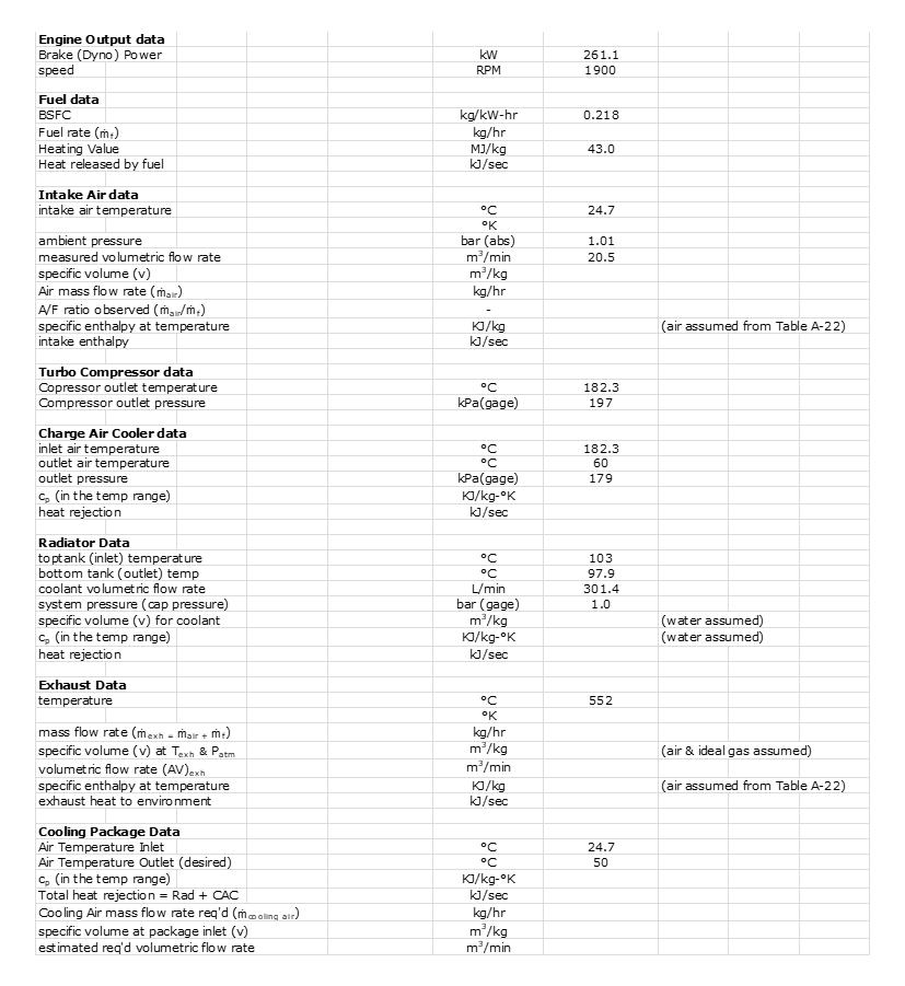
Figure 3:Suggested computations needed to establish the basic inputs for the establishing the rough specifications for the new engine application.
Expert Answer:
The provided figures give us an overview of the energy balance for an engine undergoing a dynamometer test including various inputs and outputs such as fuel chemical energy intake and exhaust air cool... View the full answer


Auditing An International Approach
ISBN: 978-1259087462
7th edition
Authors: Wally J. Smieliauskas, Kathryn Bewley
