

Question: ( 2 0 points ) In this problem, we're trying to determine the performance of two nearby radars. We will need to generate antenna patterns
points In this problem, we're trying to determine the performance of two nearby radars. We will need to generate antenna patterns uniform illumination, spacing for both radars and determine power densities and SNRs
Radar
i Frequency
ii Peak power
iii. Uniform Linear Array
length meters
iv Transmit Loss
Radar
v Frequency
vi Peak power
vii. Circular array diameter meters
viii. Duty
ix Dwell time
x Noise Figure
xi Total System Losses
xii. Bandwidth
a points Radar is turned on Calculate the Radar SNR on a dBsm target km from Radar at broadside Answer should be in dBs
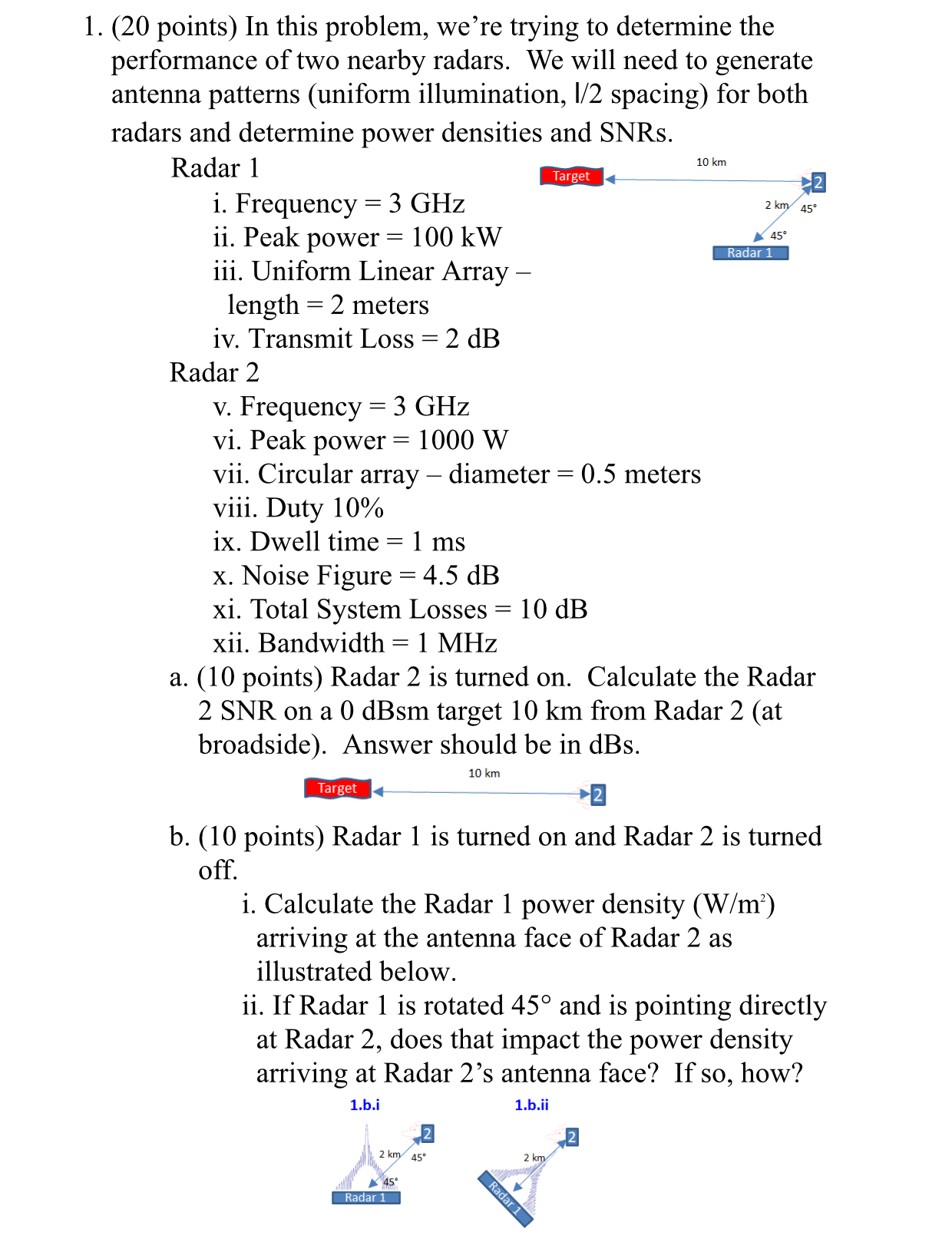
b points Radar is turned on and Radar is turned off.
i Calculate the Radar power density arriving at the antenna face of Radar as illustrated below.
ii If Radar is rotated and is pointing directly at Radar does that impact the power density arriving at Radar s antenna face? If so how?
Step by Step Solution
There are 3 Steps involved in it
1 Expert Approved Answer
Step: 1 Unlock

Question Has Been Solved by an Expert!
Get step-by-step solutions from verified subject matter experts
Step: 2 Unlock
Step: 3 Unlock