

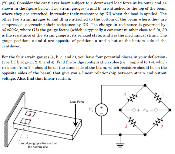
Question: ( 2 0 pts ) Consider the cantilever beam subject to a downward load force at its outer end as shown in the figure below.
pts Consider the cantilever beam subject to a downward load force at its outer end as shown in the figure below. Two strain gauges a and are attached to the top of the beam where they are stretched, increasing their resistance by DR when the load is applied. The other two strain gauges c and d are attached to the bottom of the beam where they are compressed, decreasing their resistance by DR The change in resistance is governed by: where is the gauge factor which is typically a constant number close to is the resistance of the strain gauge at its relaxed state, and is the mechanical strain. The gauge positions and are opposite of positions a and but at the bottom side of the cantilever.
For the four strain gauges a b c and d you have four potential places in your deflectiontype DC bridge and Find the bridge configuration rules ie map ad to which resistors from should be on the same side of the beam, which resistors should be on the opposite sides of the beam that give you a linear relationship between strain and output voltage. Also, find that linear relation.
Step by Step Solution
There are 3 Steps involved in it
1 Expert Approved Answer
Step: 1 Unlock

Question Has Been Solved by an Expert!
Get step-by-step solutions from verified subject matter experts
Step: 2 Unlock
Step: 3 Unlock