

Question: 2 . 1 Entity - Relationship ( ER ) Diagram The steps involved in creating the ER diagram: 1 . Entity Identification: Identify the entities
EntityRelationship ER Diagram
The steps involved in creating the ER diagram:
Entity Identification: Identify the entities involved in an online shopping market eg product, customer, order, seller, category, and listing are the main
entities. Based on the design, you may or may not need to add other entities as
well
Attribute Identification: Define attributes for each entity based on the project
requirements.
Relationship Identification: Establish relationships between entities. Decide
on relationship types onetoone, onetomany, manytomany
Cardinality and Connectivity: Determine the cardinality and connectivity
between entities in the ER diagram.
Create the ER Diagram: Utilize any diagramming tool to create a clear,
understandable ER diagram showcasing entities, attributes, and relationships.
The relations between entities at least should be as the following:
Customers should at least have a unique ID such as their TCKN and username.
Customers may have different payment methods.
Each product only belongs to one category and the amount of any product could
not be less than in the stock.
Each customer can order the same product at most three times in a single order.
Each order should have a unique ID and the order date should be added automatically when the customer completes the payment process. Additionally, there
is a status flag, which means the customer has completed the payment or not.
Each product may have different prices based on the seller.
Product alone is not purchasable by the customers. There is a product DB and if
a seller wants to sell that product, it needs to create a listing list of the products
sold by the seller from that product, specifying its stock and price.
Data Definition Language DDL SQL Code
The steps involved in writing the DDL SQL code:
DDL SQL Code Writing: Based on the ER diagram, write DDL SQL code to
create tables for each identified entity.
Include Specifications: Include primary keys, foreign keys, data types, constraints, and relationships in the SQL code.
Once you completed the database design, you should be able to do the followings in the
second part of this project By considering these queries you can modify your
design:
Note: Please note that not all of this will be asked for Part II but your DB design
should at least allow these operations.
Add a new seller
Create a new category
Add a new product
Create a new Listing
Add a new customer
Buy a Product
Update a listings price
Modify a customers address
Delete Product
Delete Seller
Delete Listing
Delete Category
Delete Customer
Remove an order from the records
Customer can addremove a payment method
Retrieve all products available in the specific category.
List all customers who have placed orders on the last dayweekmonthyear
Display all orders placed by a specific customer.
Show details of a particular product by its ID or name.
List all sellers and their contact information.
Display the total number of orders placed.
Calculate the total revenue generated by a specific product.
List topselling products based on the quantity sold.
Identify products that are out of stock or have low stock quantities.
Find product listings supplied by a specific seller.
Show the average price of products in each category.
Deliverables
The expected deliverables for this project:
ER Diagram: A visual representation of entities, their attributes, relationships,
and cardinality.
DDL SQL Code: SQL scripts to create tables, define relationships, and constraints for the database schema
DML SQL Code: SQL scripts to insert data into your tables.
Guidelines
Guidelines to ensure a successful project completion:
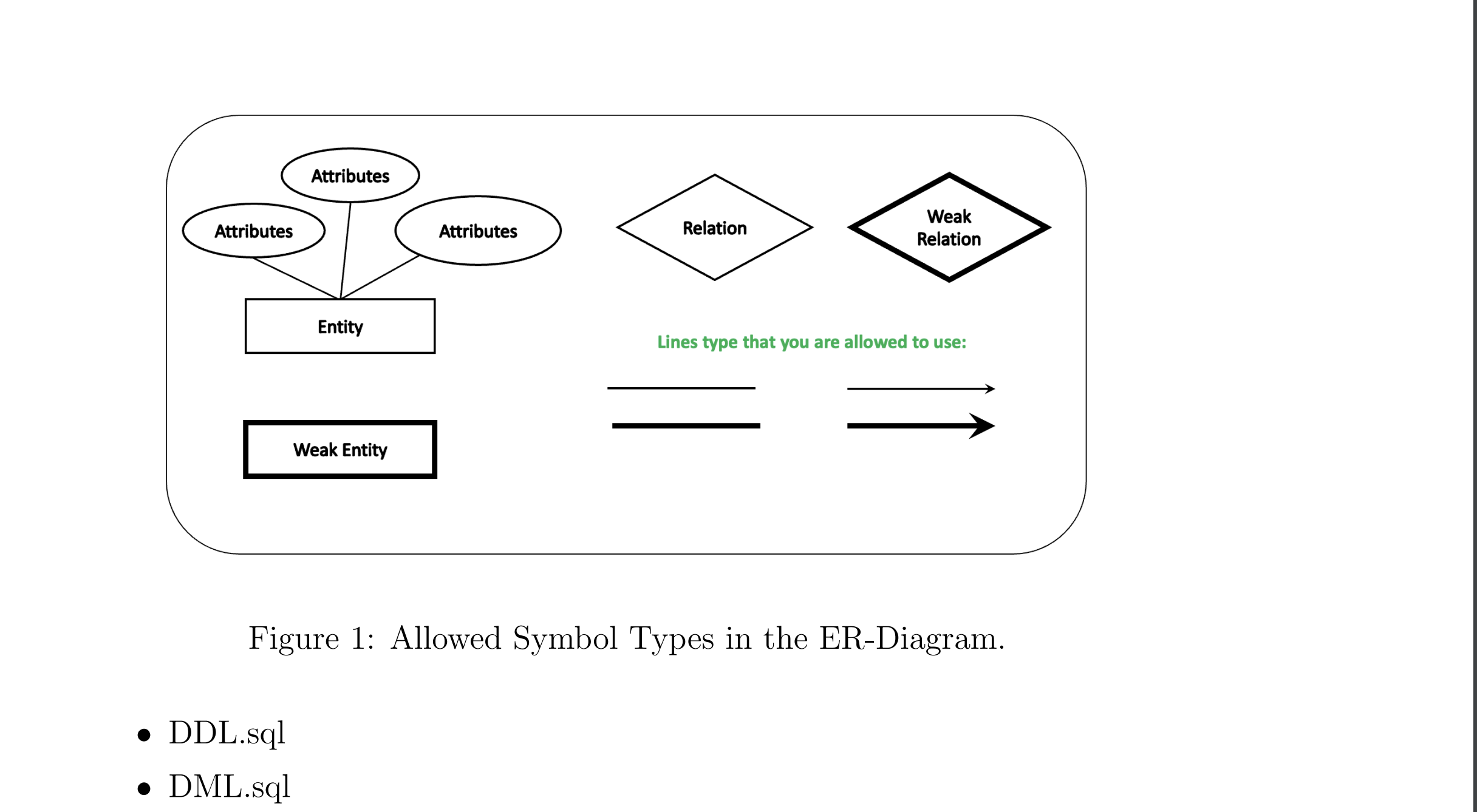
Ensure clarity and correctness in the ER diagram, representing all necessary entities and relationships. You are required to use the symbols as presented in Figure
DDL SQL code should accurately create the database schema based on the ER
diagram.
Use appropriate data types, primary and foreign keys, constraints, and naming
conventions.Figure : Allowed Symbol Types in the ERDiagram.
DDLsql
DMLsql
Step by Step Solution
There are 3 Steps involved in it
1 Expert Approved Answer
Step: 1 Unlock

Question Has Been Solved by an Expert!
Get step-by-step solutions from verified subject matter experts
Step: 2 Unlock
Step: 3 Unlock