

Question: 2 . 2 . A simple 2 - D converging nozzle can be represented by the following schematic. It starts with a center line velocity
A simple D converging nozzle can be represented by the following schematic. It starts with a
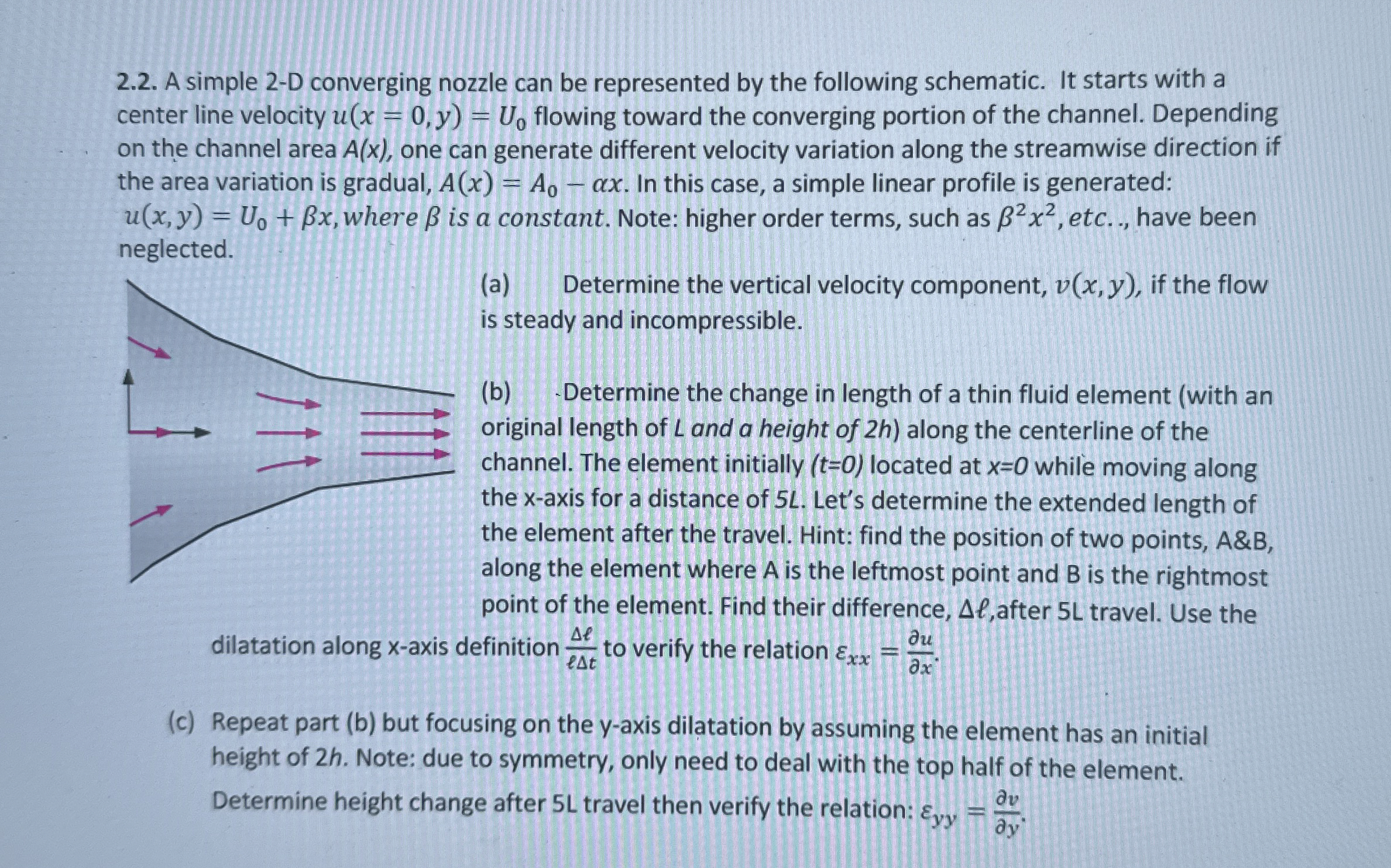
center line velocity flowing toward the converging portion of the channel. Depending
on the channel area one can generate different velocity variation along the streamwise direction if
the area variation is gradual, In this case, a simple linear profile is generated:
where is a constant. Note: higher order terms, such as etc.., have been
neglected.
a Determine the vertical velocity component, if the flow
is steady and incompressible.
b Determine the change in length of a thin fluid element with an
original length of and a height of along the centerline of the
channel. The element initially located at while moving along
the axis for a distance of Let's determine the extended length of
the element after the travel. Hint: find the position of two points, &
along the element where is the leftmost point and is the rightmost
point of the element. Find their difference, after travel. Use the
dilatation along axis definition to verify the relation
c Repeat part b but focusing on the axis dilatation by assuming the element has an initial
height of Note: due to symmetry, only need to deal with the top half of the element.
Determine height change after L travel then verify the relation:
Step by Step Solution
There are 3 Steps involved in it
1 Expert Approved Answer
Step: 1 Unlock

Question Has Been Solved by an Expert!
Get step-by-step solutions from verified subject matter experts
Step: 2 Unlock
Step: 3 Unlock