

Question: 2 - 4 Figure 2 - 4 P shows an excitation system for a synchronous generator. The generator field winding is excited by a main
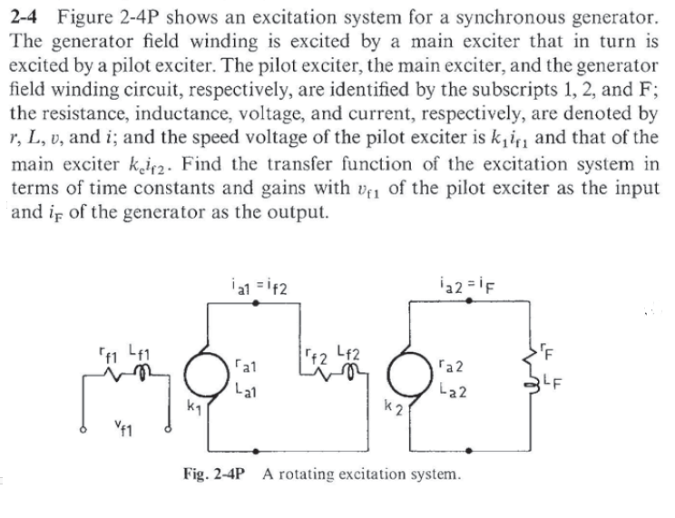
Figure P shows an excitation system for a synchronous generator. The generator field winding is excited by a main exciter that in turn is excited by a pilot exciter. The pilot exciter, the main exciter, and the generator field winding circuit, respectively, are identified by the subscripts and F ; the resistance, inductance, voltage, and current, respectively, are denoted by r L v and i ; and the speed voltage of the pilot exciter is k imathrmf and that of the main exciter kmathrme imathrmf Find the transfer function of the excitation system in terms of time constants and gains with vmathrmf of the pilot exciter as the input and imathrmF of the generator as the output.
Fig. P A rotating excitation system.
Step by Step Solution
There are 3 Steps involved in it
1 Expert Approved Answer
Step: 1 Unlock

Question Has Been Solved by an Expert!
Get step-by-step solutions from verified subject matter experts
Step: 2 Unlock
Step: 3 Unlock