

Question: 2. An electronic component schematically shown in Figure 2 is made up of two different components A and B with thermal conductivities K =
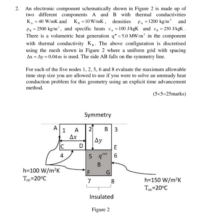
2. An electronic component schematically shown in Figure 2 is made up of two different components A and B with thermal conductivities K = 40 W/mK and K =10W/mK, densities PA = 1200 kg/m and PB = 2500 kg/m, and specific heats C = 100 J/kgK and CB = 250 J/kgK There is a volumetric heat generation q" =5.0 MW/m in the component with thermal conductivity KB. The above configuration is discretised using the mesh shown in Figure 2 where a uniform grid with spacing Ax = Ay = 0.04m is used. The side AB falls on the symmetry line. For each of the five nodes 1, 2, 5, 6 and 8 evaluate the maximum allowable time step size you are allowed to use if you were to solve an unsteady heat conduction problem for this geometry using an explicit time advancement method. (55=25marks) Symmetry A 1 A 2 B 3 Ax Ay C D E 4 5 q"" 6 B F G 7 8 h=150 W/mK Too=20C h=100 W/mK T =20C Insulated Figure 2
Step by Step Solution
There are 3 Steps involved in it

Get step-by-step solutions from verified subject matter experts