

Question: 2. An electronic component schematically shown in Figure 2 is made up of two different materials with thermal conductivities K = 50W/mK and K
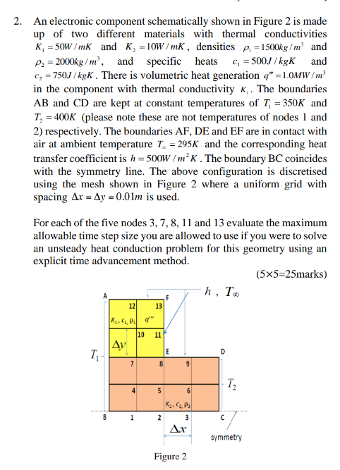
2. An electronic component schematically shown in Figure 2 is made up of two different materials with thermal conductivities K = 50W/mK and K = 10W/mK, densities p=1500kg/m and P = 2000kg/m, and specific heats c = 500J/kgK and c=750J/kgK. There is volumetric heat generation q" -1.0MW/m in the component with thermal conductivity K,. The boundaries AB and CD are kept at constant temperatures of T =350K and T = 400K (please note these are not temperatures of nodes 1 and 2) respectively. The boundaries AF, DE and EF are in contact with air at ambient temperature T = 295K and the corresponding heat transfer coefficient is h=500W/ mK. The boundary BC coincides with the symmetry line. The above configuration is discretised using the mesh shown in Figure 2 where a uniform grid with spacing Ax Ay - 0.01m is used. For each of the five nodes 3, 7, 8, 11 and 13 evaluate the maximum allowable time step size you are allowed to use if you were to solve an unsteady heat conduction problem for this geometry using an explicit time advancement method. (5x5=25marks) T B 12 K, C, P q" Ay 7 4 1 13 10 11 8 5 2 E 9 6 K, C, P 3 Ax Figure 2 h, Too T T symmetry
Step by Step Solution
There are 3 Steps involved in it
We can utilize the stability criterion for explicit techniques which is based on the CourantFriedric... View full answer

Get step-by-step solutions from verified subject matter experts