

Question: 2 B Figure Q 1 ( c ) A . Shown in Figures Q 2 ( a - i ) and Q 2 ( a
Figure Qc
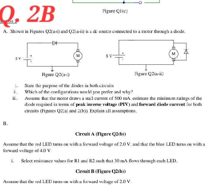
A Shown in Figures Qai and is a dc source connected to a motor through a diode.
i State the purpose of the diodes in both circuits
ii Which of the configurations would you prefer and why?
iii. Assume that the motor draws a stall current of mA estimate the minimum ratings of the diode required in terms of peak inverse voltage PIV and forward diode current for both circuits Figures Qa and b Explain all assumptions.
B
Circuit A Figure Qb
Assume that the red LED turns on with a forward voltage of V and that the blue LED turns on with a forward voltage of V
i Select resistance values for R and R such that mA flows through each LED.
Circuit B Figure Qb
Assume that the red LED turns on with a forward voltage of V
Step by Step Solution
There are 3 Steps involved in it
1 Expert Approved Answer
Step: 1 Unlock

Question Has Been Solved by an Expert!
Get step-by-step solutions from verified subject matter experts
Step: 2 Unlock
Step: 3 Unlock