

Question: 2. Case 1: Run the simulation using either R=0 or f=0Ns/m. 3. Case 2: Run the simulation using either R=0.6 or f=1Ns/m. 4. Case 3:
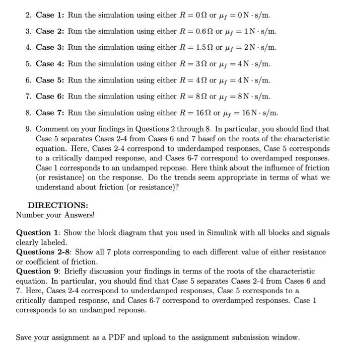
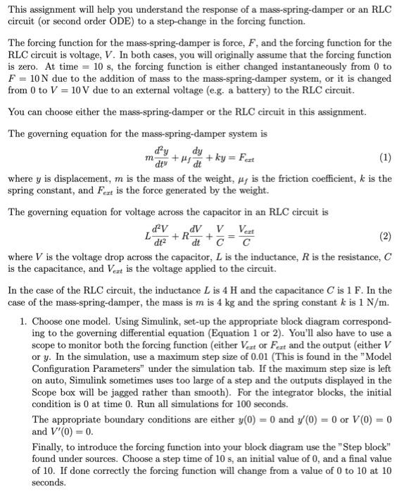
2. Case 1: Run the simulation using either R=0 or f=0Ns/m. 3. Case 2: Run the simulation using either R=0.6 or f=1Ns/m. 4. Case 3: Run the simulation using either R=1.5 or f=2Ns/m. 5. Case 4: Run the simulation using either R=3 or f=4Ns/m. 6. Case 5: Run the simulation using either R=4 or f=4Ns/m. 7. Case 6: Run the simulation using either R=8 or f=8Ns/m. 8. Case 7: Run the simulation using either R=16 or f=16Ns/m. 9. Comment on your findings in Questions 2 through 8. In particular, you should find that Case 5 separates Cases 2-4 from Cases 6 and 7 basef on the roots of the characteristic equation. Here, Cases 2-4 correspond to underdamped responses, Case 5 corresponds to a critically damped response, and Cases 6-7 correspond to overdamped responses. Case 1 corresponds to an undamped reponse. Here think about the influence of friction (or resistance) on the response. Do the trends seem appropriate in terms of what we understand about friction (or resistance)? DIRECTIONS: Number your Answers! Question 1: Show the block diagram that you used in Simulink with all blocks and signals clearly labeled. Questions 2-8: Show all 7 plots corresponding to each different value of either resistance or coefficient of friction. Question 9: Briefly discussion your findings in terms of the roots of the characteristic equation. In particular, you should find that Case 5 separates Cases 2-4 from Cases 6 and 7. Here, Cases 2-4 correspond to underdamped responses, Case 5 corresponds to a critically damped response, and Cases 6-7 correspond to overdamped responses. Case 1 corresponds to an undamped reponse. Save your assignment as a PDF and upload to the assignment submission window. This assignment will help you understand the response of a mass-spring-damper or an RLC circuit (or second order ODE) to a step-change in the forcing function. The forcing function for the mass-spring-damper is force, F, and the forcing function for the RLC circuit is voltage, V. In both cases, you will originally assume that the forcing function is zero. At time =10s, the forcing function is either changed instantaneously from 0 to F=10N due to the addition of mass to the mass-spring-damper system, or it is changed from 0 to V=10V due to an external voltage (e.g. a battery) to the RLC circuit. You can choose either the mass-spring-damper or the RLC circuit in this assignment. The governing equation for the mass-spring-damper system is mdtyd2y+fdtdy+ky=Fext where y is displacement, m is the mass of the weight, f is the friction coefficient, k is the spring constant, and Fext is the force generated by the weight. The governing equation for voltage across the capacitor in an RLC circuit is Ldt2d2V+RdtdV+CV=CVeat where V is the voltage drop across the capacitor, L is the inductance, R is the resistance, C is the capacitance, and Vext is the voltage applied to the circuit. In the case of the RLC circuit, the inductance L is 4H and the capacitance C is 1F. In the case of the mass-spring-damper, the mass is m is 4kg and the spring constant k is 1N/m. 1. Choose one model. Using Simulink, set-up the appropriate block diagram corresponding to the governing differential equation (Equation 1 or 2). You'll also have to use a scope to monitor both the forcing function (either Vext or Fext and the output (either V or y. In the simulation, use a maximum step size of 0.01 (This is found in the "Model Configuration Parameters" under the simulation tab. If the maximum step size is left on auto, Simulink sometimes uses too large of a step and the outputs displayed in the Scope box will be jagged rather than smooth). For the integrator blocks, the initial condition is 0 at time 0 . Run all simulations for 100 seconds. The appropriate boundary conditions are either y(0)=0 and y(0)=0 or V(0)=0 and V(0)=0. Finally, to introduce the forcing function into your block diagram use the "Step block" found under sources. Choose a step time of 10s, an initial value of 0 , and a final value of 10 . If done correctly the forcing function will change from a value of 0 to 10 at 10 seconds
Step by Step Solution
There are 3 Steps involved in it

Get step-by-step solutions from verified subject matter experts