

Question: 2 ) Consider the thin uniform plate shown in Figure 1 A ( next page ) . A load ( P = 3 0
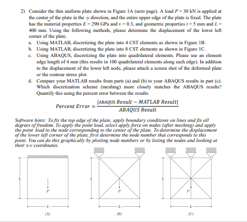
Consider the thin uniform plate shown in Figure A next page A load PmathrmkN is applied at the center of the plate in the y direction, and the entire upper edge of the plate is fixed. The plate has the material properties EmathrmGPa and v and geometric properties tmathrm~mm and L mm Using the following methods, please determine the displacement of the lower left corner of the plate.
a Using MATLAB, discretizing the plate into CST elements as shown in Figure B
b Using MATLAB, discretizing the plate into CST elements as shown in Figure C
c Using ABAQUS, discretizing the plate into quadrilateral elements. Please use an element edge length of mm this results in quadrilateral elements along each edge In addition to the displacement of the lower left node, please attach a screen shot of the deformed plate or the contour stress plot.
d Compare your MATLAB results from parts a and b to your ABAQUS results in part c Which discretization scheme meshing more closely matches the ABAQUS results? Quantify this using the pereent error between the results.
text Percent Error fracmid text ABAQuS Result text MATLAB Result midA B A Q U S text Result
Software hints: To fix the top edge of the plate, apply boundary conditions on lines and fix all degrees of freedom. To apply the point load, select apply force on nodes afier meshing and apply the point load to the node corresponding to the center of the plate. To determine the displacement of the lower left corner of the plate, first determine the node number that corresponds to this point. You can do this graphically by plotting node numbers or by listing the nodes and looking at their x v coordinates.
Step by Step Solution
There are 3 Steps involved in it
1 Expert Approved Answer
Step: 1 Unlock

Question Has Been Solved by an Expert!
Get step-by-step solutions from verified subject matter experts
Step: 2 Unlock
Step: 3 Unlock