

Question: In this part, your goal is to derive the transfer function representation for the rotational mechanical system composed of two inertias Um and JL)
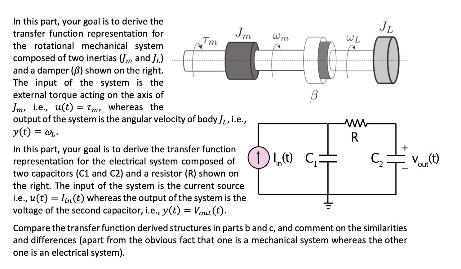
In this part, your goal is to derive the transfer function representation for the rotational mechanical system composed of two inertias Um and JL) and a damper (B) shown on the right. The input of the system is the external torque acting on the axis of Jm, i.e., u(t) = Tm, whereas the output of the system is the angular velocity of body J, i.e., y(t) = @L. Tm Jm In this part, your goal is to derive the transfer function representation for the electrical system composed of two capacitors (C1 and C2) and a resistor (R) shown on the right. The input of the system is the current source i.e., u(t) = Iin (t) whereas the output of the system is the voltage of the second capacitor, i.e., y(t) = Vout(t). Wom A I ) 1 (t) C WL www R JL O Compare the transfer function derived structures in parts b and c, and comment on the similarities and differences (apart from the obvious fact that one is a mechanical system whereas the other one is an electrical system). V(t)
Step by Step Solution
3.49 Rating (156 Votes )
There are 3 Steps involved in it
SOLUTION In part b the transfer function representation for the rotational mechanical system compose... View full answer

Get step-by-step solutions from verified subject matter experts