

Question: 2. Create a SolidWorks part file, then generate a solid model for the object shown in problem P4-22 on page 4-86 of the textbook.
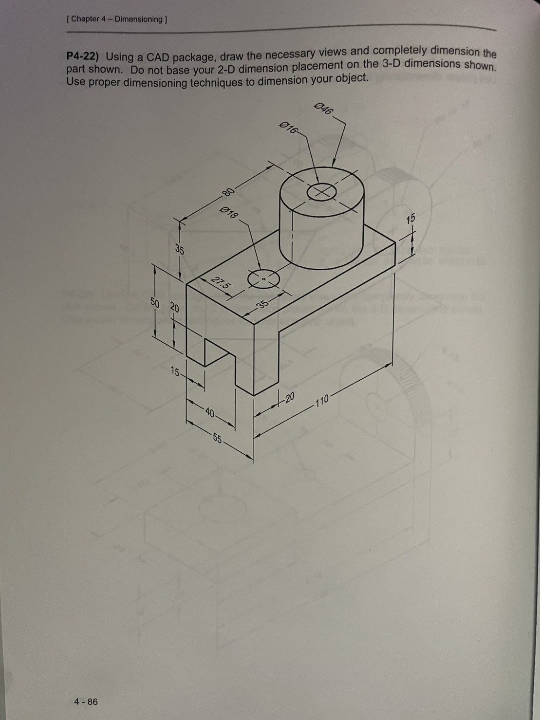
2. Create a SolidWorks part file, then generate a solid model for the object shown in problem P4-22 on page 4-86 of the textbook. Create a drawing file from your completed model, add all required views, and fully dimension the object using conventions and rules demonstrated in lecture. All dimensions are in MMGS, all sketches must be fully defined. (150 points) Use the orientation shown. The cylindrical feature on the top surface must be created using a revolved boss/base. Place Datum Feature callouts on the front, left, and top bracket surface (not the cylinder). Edit the tolerance block to add a symmetric sheet tolerance of 0.005 inches. Add a geometric position tolerance of 0.001 to the center of the cylinder. [Chapter 4 Dimensioning ] P4-22) Using a CAD package, draw the necessary views and completely dimension the part shown. Do not base your 2-D dimension placement on the 3-D dimensions shown. Use proper dimensioning techniques to dimension your object. 016- 046 018 35 27.5 50 20 +8 15- 4-86 40 55. -(+) 20 110 15
Step by Step Solution
There are 3 Steps involved in it

Get step-by-step solutions from verified subject matter experts