

Question: 2. Grading Criteria Students will be graded based on: Detailed drawing (not Quartus RTL Viewer) of data flow circuit according to the requested features -
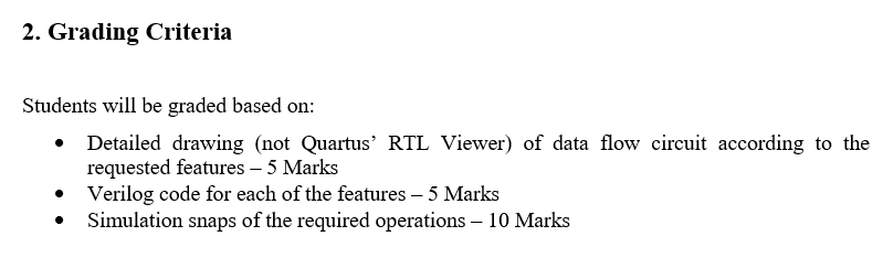
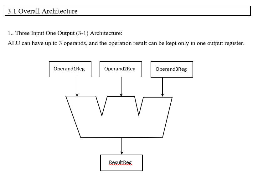
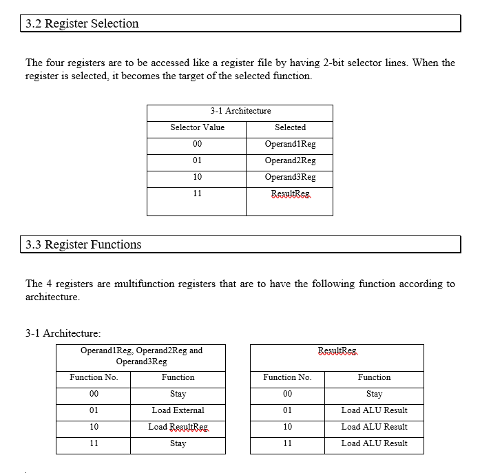
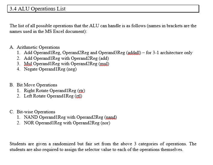
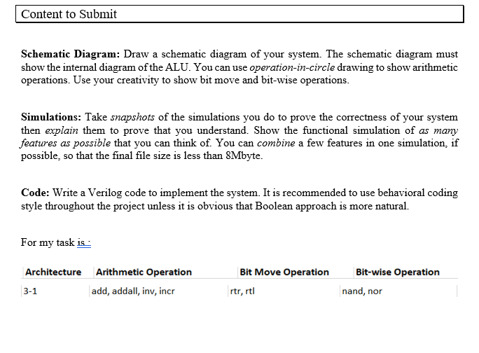
2. Grading Criteria Students will be graded based on: Detailed drawing (not Quartus RTL Viewer) of data flow circuit according to the requested features - 5 Marks Verilog code for each of the features 5 Marks Simulation snaps of the required operations 10 Marks 3.1 Overall Architecture 1.. Three Input One Output (3-1) Architecture: ALU can have up to 3 operands, and the operation result can be kept only in one output register. Operand1Reg Operand2Reg Operand3Reg ResultReg 3.2 Register Selection The four registers are to be accessed like a register file by having 2-bit selector lines. When the register is selected, it becomes the target of the selected function. 3-1 Architecture Selector Value Selected 00 01 Operand1Reg Operand2Reg Operand3Reg ResultReg 10 11 3.3 Register Functions The 4 registers are multifunction registers that are to have the following function according to architecture. 3-1 Architecture: Operand1Reg, Operand2Reg and Operand3Reg Function No. Function ResultReg. Function No. Function 00 Stay 00 Stay 01 Load External 01 Load ALU Result 10 Load ResultReg 10 Load ALU Result 11 Stay 11 Load ALU Result 3.4 ALU Operations List The list of all possible operations that the ALU can handle is as follows (names in brackets are the names used in the MS Excel document): A. Arithmetic Operations 1. Add Operand1Reg. Operand2Reg and Operand3Reg (addall) for 3-1 architecture only 2. Add Operand1Reg with Operand2Reg (add) 3. Mul Operand1Reg with Operand2Reg (mul) 4. Negate Operand1Reg (neg) B. Bit Move Operations 1. Right Rotate Operand1Reg (it) 2. Left Rotate Operand1Reg (tl) C. Bit-wise Operations 1. NAND Operand1Reg with Operand2Reg (nand) 2. NOR Operand/Reg with Operand2Reg (nor) Students are given a randomized but fair set from the above 3 categories of operations. The students are also required to assign the selector value to each of the operations themselves. Content to Submit Schematic Diagram: Draw a schematic diagram of your system. The schematic diagram must show the internal diagram of the ALU. You can use operation-in-circle drawing to show arithmetic operations. Use your creativity to show bit move and bit-wise operations. Simulations: Take snapshots of the simulations you do to prove the correctness of your system then explain them to prove that you understand. Show the functional simulation of as many features as possible that you can think of. You can combine a few features in one simulation, if possible, so that the final file size is less than 8Mbyte. Code: Write a Verilog code to implement the system. It is recommended to use behavioral coding style throughout the project unless it is obvious that Boolean approach is more natural. For my task is : Architecture Arithmetic Operation 3-1 add, addall, inv, incr Bit Move Operation rtr, rtl Bit-wise Operation nand, nor 2. Grading Criteria Students will be graded based on: Detailed drawing (not Quartus RTL Viewer) of data flow circuit according to the requested features - 5 Marks Verilog code for each of the features 5 Marks Simulation snaps of the required operations 10 Marks 3.1 Overall Architecture 1.. Three Input One Output (3-1) Architecture: ALU can have up to 3 operands, and the operation result can be kept only in one output register. Operand1Reg Operand2Reg Operand3Reg ResultReg 3.2 Register Selection The four registers are to be accessed like a register file by having 2-bit selector lines. When the register is selected, it becomes the target of the selected function. 3-1 Architecture Selector Value Selected 00 01 Operand1Reg Operand2Reg Operand3Reg ResultReg 10 11 3.3 Register Functions The 4 registers are multifunction registers that are to have the following function according to architecture. 3-1 Architecture: Operand1Reg, Operand2Reg and Operand3Reg Function No. Function ResultReg. Function No. Function 00 Stay 00 Stay 01 Load External 01 Load ALU Result 10 Load ResultReg 10 Load ALU Result 11 Stay 11 Load ALU Result 3.4 ALU Operations List The list of all possible operations that the ALU can handle is as follows (names in brackets are the names used in the MS Excel document): A. Arithmetic Operations 1. Add Operand1Reg. Operand2Reg and Operand3Reg (addall) for 3-1 architecture only 2. Add Operand1Reg with Operand2Reg (add) 3. Mul Operand1Reg with Operand2Reg (mul) 4. Negate Operand1Reg (neg) B. Bit Move Operations 1. Right Rotate Operand1Reg (it) 2. Left Rotate Operand1Reg (tl) C. Bit-wise Operations 1. NAND Operand1Reg with Operand2Reg (nand) 2. NOR Operand/Reg with Operand2Reg (nor) Students are given a randomized but fair set from the above 3 categories of operations. The students are also required to assign the selector value to each of the operations themselves. Content to Submit Schematic Diagram: Draw a schematic diagram of your system. The schematic diagram must show the internal diagram of the ALU. You can use operation-in-circle drawing to show arithmetic operations. Use your creativity to show bit move and bit-wise operations. Simulations: Take snapshots of the simulations you do to prove the correctness of your system then explain them to prove that you understand. Show the functional simulation of as many features as possible that you can think of. You can combine a few features in one simulation, if possible, so that the final file size is less than 8Mbyte. Code: Write a Verilog code to implement the system. It is recommended to use behavioral coding style throughout the project unless it is obvious that Boolean approach is more natural. For my task is : Architecture Arithmetic Operation 3-1 add, addall, inv, incr Bit Move Operation rtr, rtl Bit-wise Operation nand, nor
Step by Step Solution
There are 3 Steps involved in it

Get step-by-step solutions from verified subject matter experts