

Question: 2. Pipeline Simulation For each of the modules from Figure 4.51 (page 304 of P&H) that are listed in the table below, specify what the
2. Pipeline Simulation For each of the modules from Figure 4.51 (page 304 of P&H) that are listed in the table below, specify what the inputs and outputs are in each cycle for the following code. You do not need to specify values for those modules, inputs, or outputs not listed in the table. Manually simulate (i.e., fill out the table) until the sw has completed (i.e., left the write-back stage). [Hint: the table already has the first couple of cycles filled out. If a value depends on an instruction before or after the code below, report it as X.]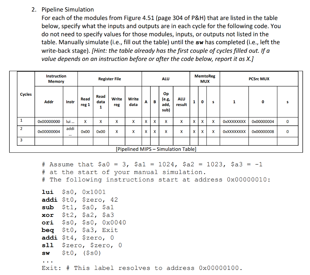
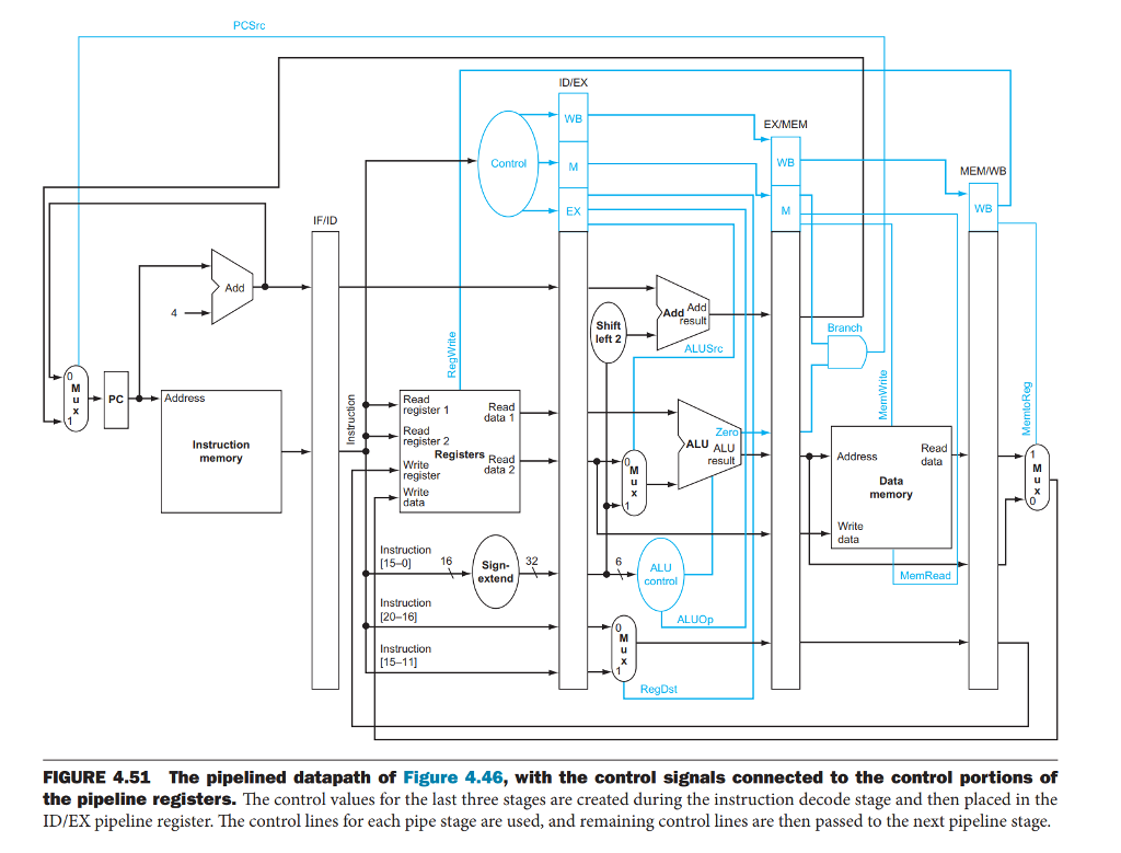
2. Pipeline Simulation For each of the modules from Figure 4.51 (page 304 of P&H) that are listed in the table below, specify what the inputs and outputs are in each cycle for the following code. You do not need to specify values for those modules, inputs, or outputs not listed in the table. Manually simulate (i.e., fill out the table) until the sw has completed (i.e., left the write-back stage). [Hint: the table already has the first couple of cycles filled out. If a value depends on an instruction before or after the code below, report it as X.) Instruction Memory MemtoReg MUX Register File ALU PCSrc MUX Cycles Read WriteWrite A B (e.g,ALU Addr Instr Read Read data d, result sub) re 0x00000000 lui... X XXOxXXXXXXXX 0x00000004 0x00000004 00004 addi 0x00 0x00 0x00000008 [Pipelined MIPS - Simulation Table] # Assume that $a0 = 3, $a1 = 1024, $a2 = 1023, $a3 = -1 # at the start of your manual simulation. # The following instructions start at address 0x00000010: lui $s0, 0x1001 addi St0, Szero, 42 xor $t2, $a2, $a3 ori ?s0, $s0, 0x0040 beq $t0, $a3, Exit addi $t4, $zero, 0 sll $zero, $zero, 0 sw $t0, ($s0) Exit: # This iabei resolves to address 0x00000100 2. Pipeline Simulation For each of the modules from Figure 4.51 (page 304 of P&H) that are listed in the table below, specify what the inputs and outputs are in each cycle for the following code. You do not need to specify values for those modules, inputs, or outputs not listed in the table. Manually simulate (i.e., fill out the table) until the sw has completed (i.e., left the write-back stage). [Hint: the table already has the first couple of cycles filled out. If a value depends on an instruction before or after the code below, report it as X.) Instruction Memory MemtoReg MUX Register File ALU PCSrc MUX Cycles Read WriteWrite A B (e.g,ALU Addr Instr Read Read data d, result sub) re 0x00000000 lui... X XXOxXXXXXXXX 0x00000004 0x00000004 00004 addi 0x00 0x00 0x00000008 [Pipelined MIPS - Simulation Table] # Assume that $a0 = 3, $a1 = 1024, $a2 = 1023, $a3 = -1 # at the start of your manual simulation. # The following instructions start at address 0x00000010: lui $s0, 0x1001 addi St0, Szero, 42 xor $t2, $a2, $a3 ori ?s0, $s0, 0x0040 beq $t0, $a3, Exit addi $t4, $zero, 0 sll $zero, $zero, 0 sw $t0, ($s0) Exit: # This iabei resolves to address 0x00000100
Step by Step Solution
There are 3 Steps involved in it

Get step-by-step solutions from verified subject matter experts