

Question: 3 . ( 4 0 pts ) Figure 2 It is intended to automatically maintain the liquid level in the gravity drain double water tank
pts
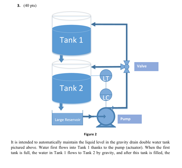
Figure
It is intended to automatically maintain the liquid level in the gravity drain double water tank pictured above. Water first flows into Tank thanks to the pump actuator When the first tank is full, the water in Tank flows to Tank by gravity, and after this tank is filled, the water returns to the reservoir. This cycle continues like this. The valve in the figure can be used as a disturbance, and thanks to this valve, water can be filled directly to Tank Here LT Level Transmitter is a sensor LC Level Controller sends a signal to the pump.
p Obtain the block diagram of the system including the controller
p Obtain FOPDTFirst order plus dead time model of the system
Fitting technique with graphical method using step test can be used. See Figure and Figure Height will be taken as output. The graph of this situation is also given in Figure Data is also given to obtain the figure. See "data.txt
p Design your own PI or PID controller for acceptable performance. Explain the design details clearly.
Figure Step response of the system Figure Input pump and Output height
Step by Step Solution
There are 3 Steps involved in it
1 Expert Approved Answer
Step: 1 Unlock

Question Has Been Solved by an Expert!
Get step-by-step solutions from verified subject matter experts
Step: 2 Unlock
Step: 3 Unlock