

Question: - = = - 3. A machine has the state diagram shown below, where N and D are the two inputs and N=D=1 cannot occur.
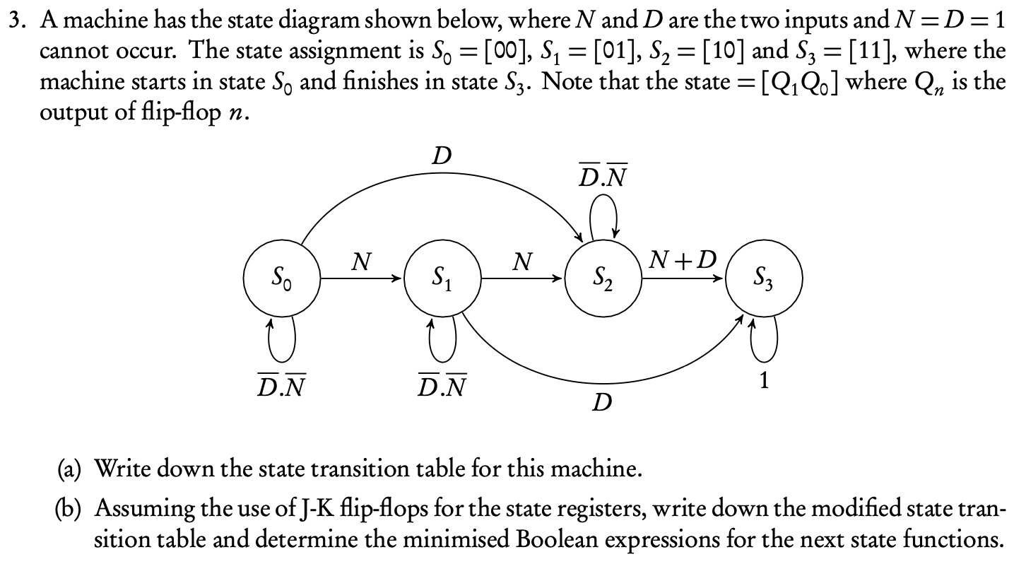
- = = - 3. A machine has the state diagram shown below, where N and D are the two inputs and N=D=1 cannot occur. The state assignment is So =[00], S1 = [01], S2 = [10] and Sz = [11], where the machine starts in state So and finishes in state Sz. Note that the state =[Q1Qe] where Qn is the output of flip-flop n. = D DN N N N +D S. Si S Sz D.N D.N 1 D (a) Write down the state transition table for this machine. (b) Assuming the use of J-K flip-flops for the state registers, write down the modified state tran- sition table and determine the minimised Boolean expressions for the next state functions
Step by Step Solution
There are 3 Steps involved in it
1 Expert Approved Answer
Step: 1 Unlock

Question Has Been Solved by an Expert!
Get step-by-step solutions from verified subject matter experts
Step: 2 Unlock
Step: 3 Unlock