

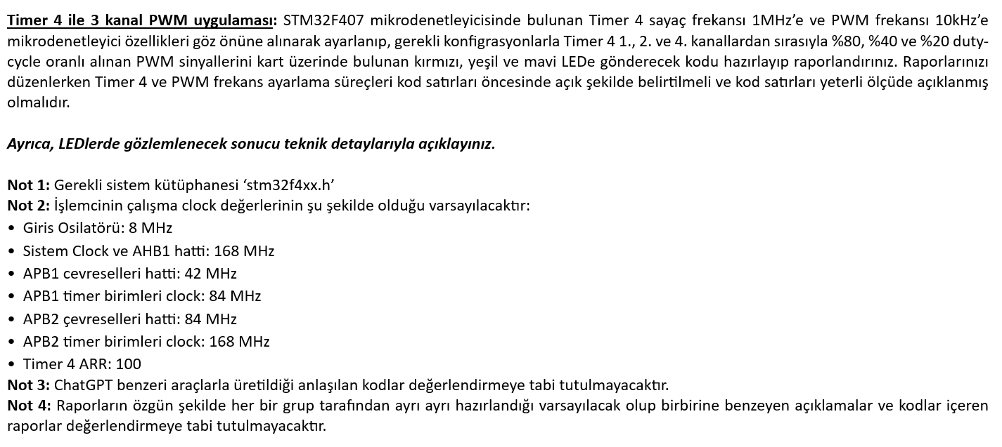
Question: 3 Channel PWM application with Timer 4 : The Timer 4 counter frequency on the STM 3 2 F 4 0 7 microcontroller is up
Channel PWM application with Timer : The Timer counter frequency on the STMF microcontroller is up to MHz and the PWM frequency is up to kHz
timer with the necessary configurations, adjusted taking into account the characteristics of the microcontroller., and and duty from channels respectively
prepare and report the code that will send the received PWM signals with cycle rate to the red, green and blue LED on the card. Your Reports
when editing, the Timer and PWM frequency adjustment processes should be clearly indicated before the lines of code, and the lines of code should be adequately explained
should be
Also, please explain the result to be observed on the LEDs in technical details.
Note : The required system library is stmfxxh
Note : It will be assumed that the operating clock values of the processor are as follows:
Input Oscillator: MHz
System Clock and AHB line: MHz
APB peripheral line: MHz
APB timer units clock: MHz
APB peripheral line: MHz
APB timer units clock: MHz
Timer ARR:
Note : Codes that are understood to be produced with ChatGPTlike tools will not be subject to evaluation.
Note : It will be assumed that the reports are originally prepared separately by each group and contain similar descriptions and codes
the reports will not be subject to evaluation.
Step by Step Solution
There are 3 Steps involved in it
1 Expert Approved Answer
Step: 1 Unlock

Question Has Been Solved by an Expert!
Get step-by-step solutions from verified subject matter experts
Step: 2 Unlock
Step: 3 Unlock