

Question: 3. Consider the given ladder logic diagram and answer the following questions when the CPU is in a RUN mode and neither one of the
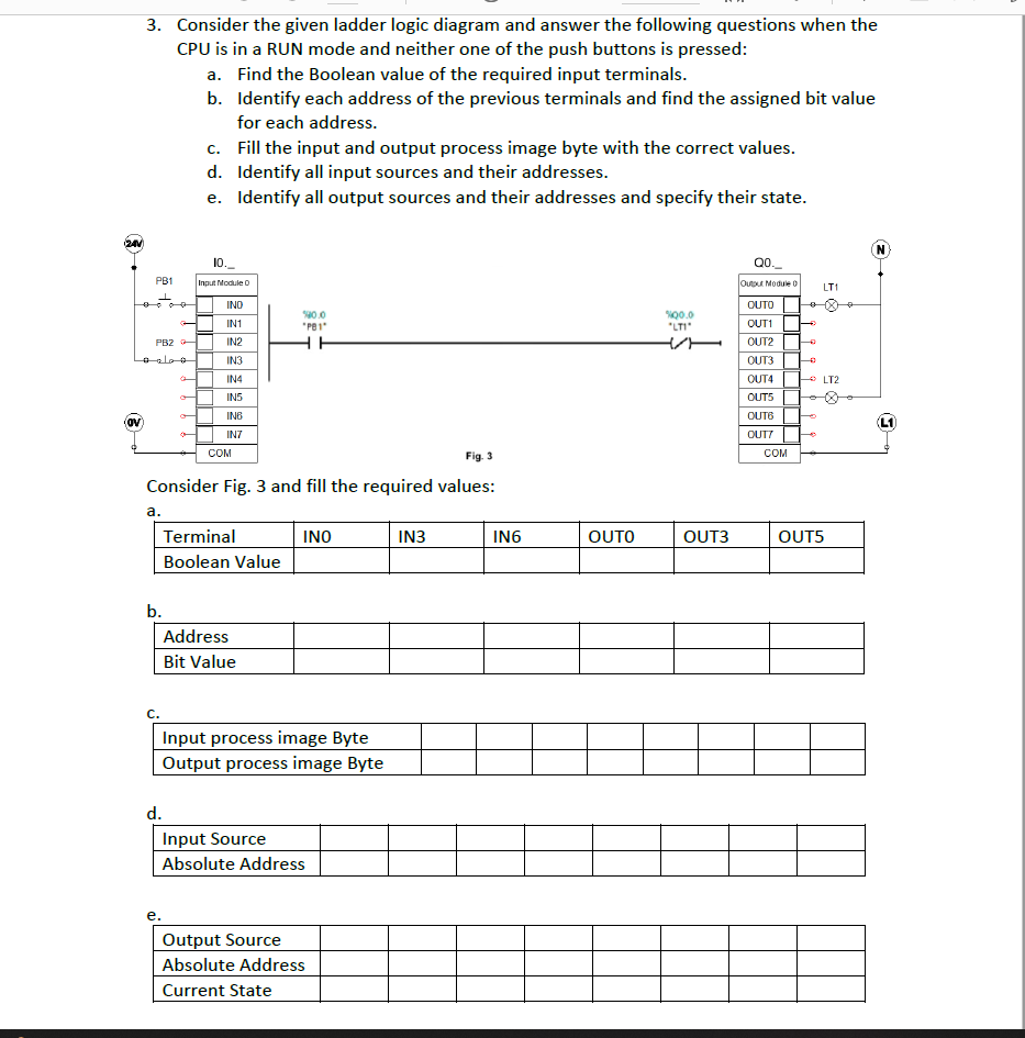
3. Consider the given ladder logic diagram and answer the following questions when the CPU is in a RUN mode and neither one of the push buttons is pressed: a. Find the Boolean value of the required input terminals. b. Identify each address of the previous terminals and find the assigned bit value for each address. C. Fill the input and output process image byte with the correct values. d. Identify all input sources and their addresses. e. Identify all output sources and their addresses and specify their state. 2 N 10._ Q0. PB1 Input Module Output Module LT1 INO OUTO 0 IN1 90.0 "P81" 900.0 "LTI PB2 IN2 IN3 OUT OUT2 OUT3 OUT4 OUT5 OUTS IN4 - LT2 INS INB OV L1 IN7 OUTY COM COM Fig. 3 Consider Fig. 3 and fill the required values: a. Terminal INO IN3 IN6 Boolean Value OUTO OUT3 OUT5 b. Address Bit Value C. Input process image Byte Output process image Byte d. Input Source Absolute Address e. Output Source Absolute Address Current State
Step by Step Solution
There are 3 Steps involved in it

Get step-by-step solutions from verified subject matter experts