

Question: 3. Consider the LRC circuit shown below. Use = = 10V, R1 = 20, R2 is a variable resistor initially set to 50, C1 =
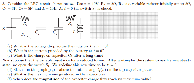
3. Consider the LRC circuit shown below. Use = = 10V, R1 = 20, R2 is a variable resistor initially set to 50, C1 = 3F, C2 = 5F, and L = 10H. At t = 0 the switch S1 is closed. WW MAAAN R R, L S, (a) What is the voltage drop across the inductor L at t = 0? (b) What is the current provided by the battery at t = 0? (c) What is the charge on capacitor Ci after a long time? Now suppose that the variable resistance R2 is reduced to zero. After waiting for the system to reach a new steady state, we open the switch S1. We redefine this new time to be f' = 0. (d) Sketch on the graph paper above the total charge Q(t') on the top capacitor plates. (e) What is the maximum energy stored in the capacitors? (f) When does the magnitude of the capacitor charge first reach its maximum value
Step by Step Solution
There are 3 Steps involved in it

Get step-by-step solutions from verified subject matter experts