

Question: 3. How do we realize 24 decoder with logic gates? Use the truth table in Figure 3.3. 4. Realize f(A,B)=(0,2,3) with 24 Decoder. (Feed 16
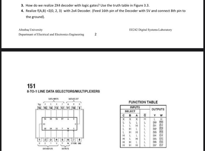
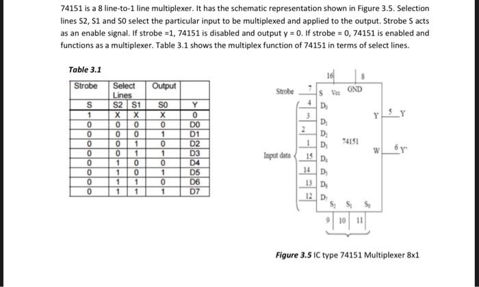
3. How do we realize 24 decoder with logic gates? Use the truth table in Figure 3.3. 4. Realize f(A,B)=(0,2,3) with 24 Decoder. (Feed 16 th pin of the Decoder with 5V and connect 8th pin to the ground). Altinbas University EE242 Digital Systems Laboratory Departmant of Electrical and Electronics Engineering 2 151 8-TO-1 LINE DATA SELECTORSMMULTIPLEXERS FUNCTION TARLE 74151 is a 8 line-to-1 line multiplexer. It has the schematic representation shown in Figure 3.5. Selection lines S2,S1 and S0 select the particular input to be multiplexed and applied to the output. Strobe S acts as an enable signal. If strobe =1,74151 is disabled and output y=0. If strobe =0,74151 is enabled and functions as a multiplexer. Table 3.1 shows the multiplex function of 74151 in terms of select lines. Table 3.1 Figure 3.5 IC type 74151 Multiplexer 81 Runctiow TaButs 24ist-To-4uat btcooth On subt-10 - trat brevtlifiext
Step by Step Solution
There are 3 Steps involved in it

Get step-by-step solutions from verified subject matter experts