

Question: 3 : Inside your Q 2 folder, you are going to use a different approach to describe the 2 - digit BCD adder. No longer
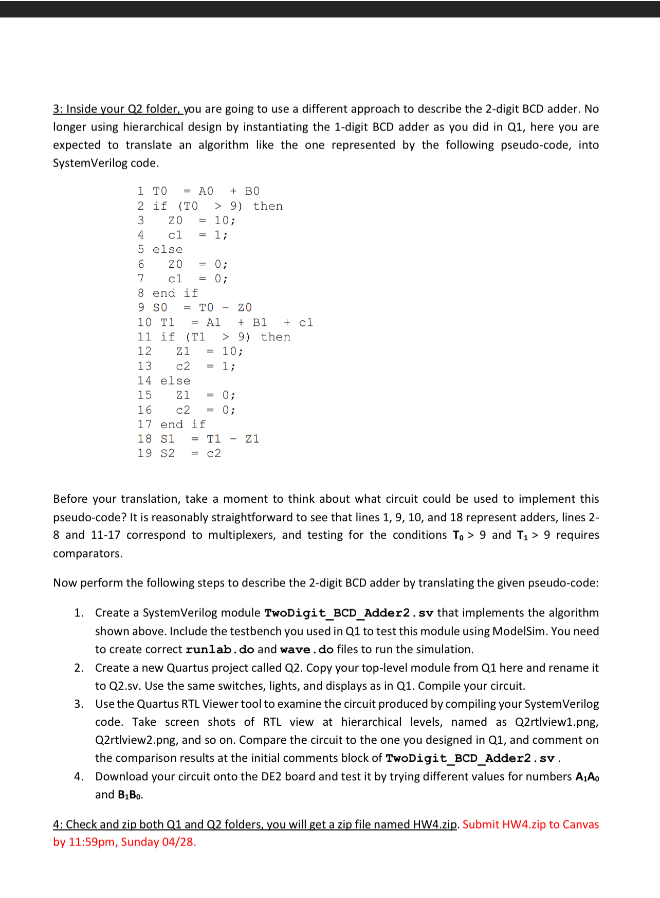
: Inside your Q folder, you are going to use a different approach to describe the digit BCD adder. No longer using hierarchical design by instantiating the digit BCD adder as you did in Q here you are expected to translate an algorithm like the one represented by the following pseudocode, into SystemVerilog code.Before your translation, take a moment to think about what circuit could be used to implement this pseudocode? It is reasonably straightforward to see that lines and represent adders, lines and correspond to multiplexers, and testing for the conditions T and T requires comparators.
Now perform the following steps to describe the digit BCD adder by translating the given pseudocode:
Create a SystemVerilog module TwoDigitBCDAddersv that implements the algorithm shown above. Include the testbench you used in Q to test this module using ModelSim. You need to create correct runlab. do and wave. do files to run the simulation.
Create a new Quartus project called Q Copy your toplevel module from Q here and rename it to
Qsv Use the same switches, lights, and displays as in Q Compile your circuit.
Use the Quartus RTL Viewer tool to examine the circuit produced by compiling your SystemVerilog code. Take screen shots of RTL view at hierarchical levels, named as Qrtlviewpng Qrtlviewpng and so on Compare the circuit to the one you designed in Q and comment on the comparison results at the initial comments block of TwoDigitBCDAddersv
Download your circuit onto the DE board and test it by trying different values for numbers and
: Check and zip both Q and Q folders, you will get a zip file named HWzip. Submit HWzip to Canvas by : pm Sunday
Step by Step Solution
There are 3 Steps involved in it
1 Expert Approved Answer
Step: 1 Unlock

Question Has Been Solved by an Expert!
Get step-by-step solutions from verified subject matter experts
Step: 2 Unlock
Step: 3 Unlock