

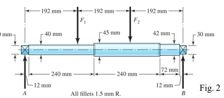
Question: 3 . The machine shaft shown in Fig. 2 is made of 1 0 9 5 HR steel, and is supported by roller bearings at
The machine shaft shown in Fig. is made of HR steel, and is supported by roller bearings at A and B The shaft is subjected to constant bending forces of F kN and F kN as well as a constant torque Tx kNm along the entire length of the shaft section with the mm diameter. Determine the critical location on the shaft, calculate the mean and cyclic stresses at this location, and finally determine the fatigue factor of safety using the Soderberg criteria. All fillets mmR
Step by Step Solution
There are 3 Steps involved in it
1 Expert Approved Answer
Step: 1 Unlock

Question Has Been Solved by an Expert!
Get step-by-step solutions from verified subject matter experts
Step: 2 Unlock
Step: 3 Unlock