

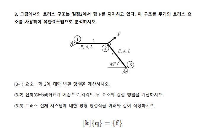
Question: 3 . The truss structure in Figure supports the force F at point 2 . Analyze this structure by finite element method with two truss
The truss structure in Figure supports the force F at point Analyze this structure by finite element method with two truss elements.
Calculate the transformation matrix for elements and
Calculate the stiffness matrix of each of the two elements based on the global coordinate system.
Write the equilibrium equation for the whole truss system as below.
kqf
Use boundary conditions to express u and v displacement values using F L E and A
Use u and v obtained from to express Fx Fy Fx and Fy using F only.
Use F L E and A to express the displacement of each node in the local coordinate system in element
In element use only F to express the strength of each node in the local coordinate system.
Step by Step Solution
There are 3 Steps involved in it
1 Expert Approved Answer
Step: 1 Unlock

Question Has Been Solved by an Expert!
Get step-by-step solutions from verified subject matter experts
Step: 2 Unlock
Step: 3 Unlock