

Question: 4. Figure 5 shows a mechanical power transmission using geared system. Electric motor A delivering power to appliance at though gears at B, C,
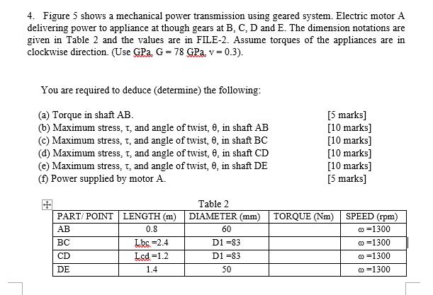
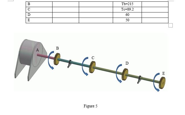
4. Figure 5 shows a mechanical power transmission using geared system. Electric motor A delivering power to appliance at though gears at B, C, D and E. The dimension notations are given in Table 2 and the values are in FILE-2. Assume torques of the appliances are in clockwise direction. (Use GPa, G= 78 GPa, v = 0.3). You are required to deduce (determine) the following: (a) Torque in shaft AB. (b) Maximum stress, T, and angle of twist, 0, in shaft AB (c) Maximum stress, T, and angle of twist, 0, in shaft BC (d) Maximum stress, t, and angle of twist, 0, in shaft CD (e) Maximum stress, t, and angle of twist, 0, in shaft DE (f) Power supplied by motor A. [5 marks] [10 marks] [10 marks] [10 marks] [10 marks] [5 marks] Table 2 PART/ POINT LENGTH (m) DIAMETER (mm) TORQUE (Nm) SPEED (rpm) o =1300 o =1300 AB 0.8 60 Lbc =2.4 Lcd =1.2 BC D1 =83 CD D1 =83 o =1300 DE 1.4 50 0 =1300 Tb=215 C Tc=89,2 60 E 50 D E Figure 5
Step by Step Solution
3.33 Rating (153 Votes )
There are 3 Steps involved in it
To solve this problem follow these steps a Torque in Shaft AB The torque T at B is given as TB 215 t... View full answer

Get step-by-step solutions from verified subject matter experts