

Question: 4. The figure (1) illustrates automatic water level control system controlled with proportional only controller. The controller is adjusted with set point of 750 mm
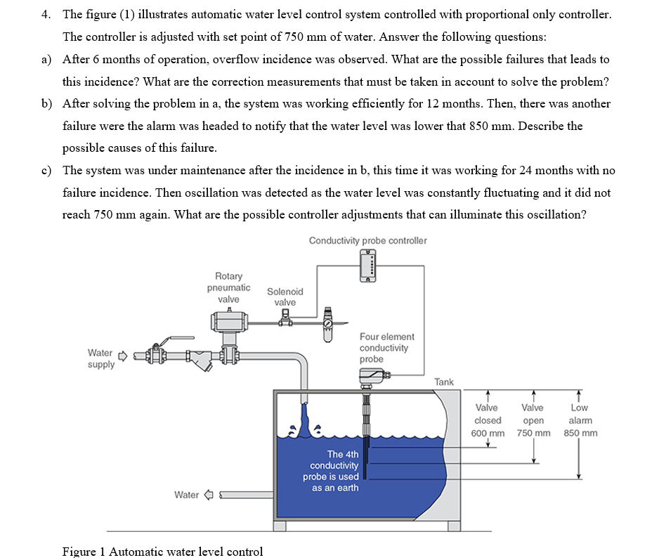
4. The figure (1) illustrates automatic water level control system controlled with proportional only controller. The controller is adjusted with set point of 750 mm of water. Answer the following questions: a) After 6 months of operation, overflow incidence was observed. What are the possible failures that leads to this incidence? What are the correction measurements that must be taken in account to solve the problem? b) After solving the problem in a, the system was working efficiently for 12 months. Then, there was another failure were the alarm was headed to notify that the water level was lower that 850 mm. Describe the possible causes of this failure. c) The system was under maintenance after the incidence in b, this time it was working for 24 months with no failure incidence. Then oscillation was detected as the water level was constantly fluctuating and it did not reach 750 mm again. What are the possible controller adjustments that can illuminate this oscillation? Conductivity probe controller Rotary pneumatic valve Solenoid valve TO Water supply Four element conductivity probe Tank Valve Valve Low closed open alarm 600 mm 750 mm 850 mm The 4th conductivity probe is used as an earth Water Figure 1 Automatic water level control 4. The figure (1) illustrates automatic water level control system controlled with proportional only controller. The controller is adjusted with set point of 750 mm of water. Answer the following questions: a) After 6 months of operation, overflow incidence was observed. What are the possible failures that leads to this incidence? What are the correction measurements that must be taken in account to solve the problem? b) After solving the problem in a, the system was working efficiently for 12 months. Then, there was another failure were the alarm was headed to notify that the water level was lower that 850 mm. Describe the possible causes of this failure. c) The system was under maintenance after the incidence in b, this time it was working for 24 months with no failure incidence. Then oscillation was detected as the water level was constantly fluctuating and it did not reach 750 mm again. What are the possible controller adjustments that can illuminate this oscillation? Conductivity probe controller Rotary pneumatic valve Solenoid valve TO Water supply Four element conductivity probe Tank Valve Valve Low closed open alarm 600 mm 750 mm 850 mm The 4th conductivity probe is used as an earth Water Figure 1 Automatic water level control
Step by Step Solution
There are 3 Steps involved in it

Get step-by-step solutions from verified subject matter experts