

Question: _ 5 3 7 7 . 4 . The gear train shown in Fig. P 7 . 4 is arranged to feed lumber between the
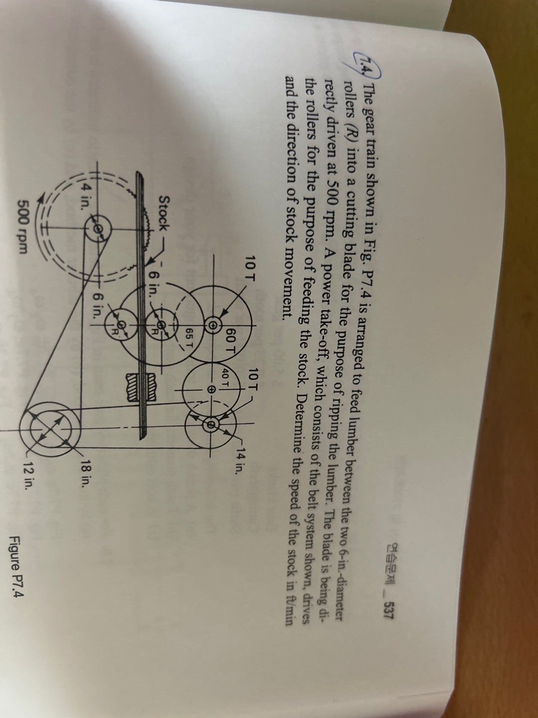
The gear train shown in Fig. P is arranged to feed lumber between the two indiameter rollers into a cutting blade for the purpose of ripping the lumber. The blade is being directly driven at rpm A power takeoff, which consists of the belt system shown, drives the rollers for the purpose of feeding the stock. Determine the speed of the stock in fumin and the direction of stock movement.
Figure P
Step by Step Solution
There are 3 Steps involved in it
1 Expert Approved Answer
Step: 1 Unlock

Question Has Been Solved by an Expert!
Get step-by-step solutions from verified subject matter experts
Step: 2 Unlock
Step: 3 Unlock