

Question: 5 . As shown in a cross - sectional view in the sketch below, two identical tubes are soldered together with a high thermal conductivity
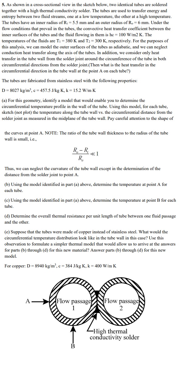
As shown in a crosssectional view in the sketch below, two identical tubes are soldered together with a high thermal conductivity solder. The tubes are used to transfer energy and entropy between two fluid streams, one at a low temperature, the other at a high temperature. The tubes have an inner radius of Rimathrm~mm and an outer radius of Romathrm~mm Under the flow conditions that prevail in the tubes, the convective heat transfer coefficient between the inner surfaces of the tubes and the fluid flowing in them is hc mathrm~Wmathrmmmathrm~K The temperatures of the fluids are mathrmTmathrm~K and mathrmTmathrm~K respectively. For the purposes of this analysis, we can model the outer surfaces of the tubes as adiabatic, and we can neglect conduction heat transfer along the axis of the tubes. In addition, we consider only heat transfer in the tube wall from the solder joint around the circumference of the tube in both circumferential directions from the solder joint.Then what is the heat transfer in the circumferential direction in the tube wall at the point A on each tube?
The tubes are fabricated from stainless steel with the following properties:
mathrmDmathrm~kgmathrmmmathrmcmathrm~Jmathrmkgmathrm~Kmathrmkmathrm~Wmathrmmmathrm~K
a For this geometry, identify a model that would enable you to determine the circumferential temperature profile in the wall of the tube. Using this model, for each tube, sketch not plot the temperature along the tube wall vs the circumferential distance from the solder joint as measured in the midplane of the tube wall. Pay careful attention to the shape of
the curves at point A NOTE: The ratio of the tube wall thickness to the radius of the tube wall is small, ie
fracRoRiRoll
Thus, we can neglect the curvature of the tube wall except in the determination of the distance from the solder joint to point A
b Using the model identified in part a above, determine the temperature at point A for each tube.
c Using the model identified in part a above, determine the temperature at point B for each tube.
d Determine the overall thermal resistance per unit length of tube between one fluid passage and the other.
e Suppose that the tubes were made of copper instead of stainless steel. What would the circumferential temperature distribution look like in the tube wall in this case? Use this observation to formulate a simpler thermal model that would allow us to arrive at the answers for parts b through d for this new material? Answer parts b through d for this new model.
For copper: mathrmDmathrm~kgmathrmmmathrmcmathrm~JmathrmkgmathrmKmathrmkmathrm~WmathrmmmathrmK
Step by Step Solution
There are 3 Steps involved in it
1 Expert Approved Answer
Step: 1 Unlock

Question Has Been Solved by an Expert!
Get step-by-step solutions from verified subject matter experts
Step: 2 Unlock
Step: 3 Unlock