

Question: 5 . Converting Strings to Lower Case The figure below shows the datapath for an FSM that converts any upper - case letters in an
Converting Strings to Lower Case
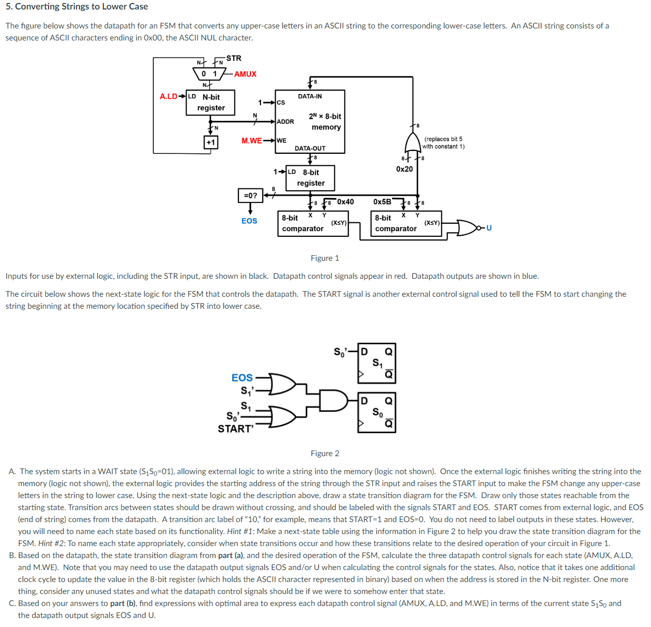
The figure below shows the datapath for an FSM that converts any uppercase letters in an ASCII string to the corresponding lowercase letters. An ASCII string consists of a sequence of A S C I I characters ending in times the A S C I I N U L character.
Figure
Inputs for use by external logic, including the STR input, are shown in black. Datapath control signals appear in red. Datapath outputs are shown in blue.
The circuit below shows the nextstate logic for the FSM that controls the datapath. The START signal is another external control signal used to tell the FSM to start changing the string beginning at the memory location specified by STR into lower case.
Figure
A The system starts in a WAIT state leftS Sright allowing external logic to write a string into the memory logic not shown Once the external logic finishes writing the string into the memory logic not shown the external logic provides the starting address of the string through the STR input and raises the START input to make the FSM change any uppercase letters in the string to lower case. Using the nextstate logic and the description above, draw a state transition diagram for the FSM Draw only those states reachable from the starting state. Transition arcs between states should be drawn without crossing, and should be labeled with the signals START and EOS. START comes from external logic, and EOS end of string comes from the datapath. A transition arc label of for example, means that START and EOS You do not need to label outputs in these states. However, you will need to name each state based on its functionality. Hint #: Make a nextstate table using the information in Figure to help you draw the state transition diagram for the FSM Hint #: To name each state appropriately, consider when state transitions occur and how these transitions relate to the desired operation of your circuit in Figure
B Based on the datapath, the state transition diagram from part a and the desired operation of the FSM calculate the three datapath control signals for each state AMUX ALD and MWE Note that you may need to use the datapath output signals EOS andor U when calculating the control signals for the states. Also, notice that it takes one additional clock cycle to update the value in the bit register which holds the ASCII character represented in binary based on when the address is stored in the Nbit register. One more thing, consider any unused states and what the datapath control signals should be if we were to somehow enter that state.
C Based on your answers to part b find expressions with optimal area to express each datapath control signal AMUX ALD and MWE in terms of the current state mathrmSmathrm~S and the datapath output signals EOS and U
Step by Step Solution
There are 3 Steps involved in it
1 Expert Approved Answer
Step: 1 Unlock

Question Has Been Solved by an Expert!
Get step-by-step solutions from verified subject matter experts
Step: 2 Unlock
Step: 3 Unlock