

Question: 5. Design a circuit that implement the state diagram shown. The circuit has one input signal W and one output signal Z. Directed edges
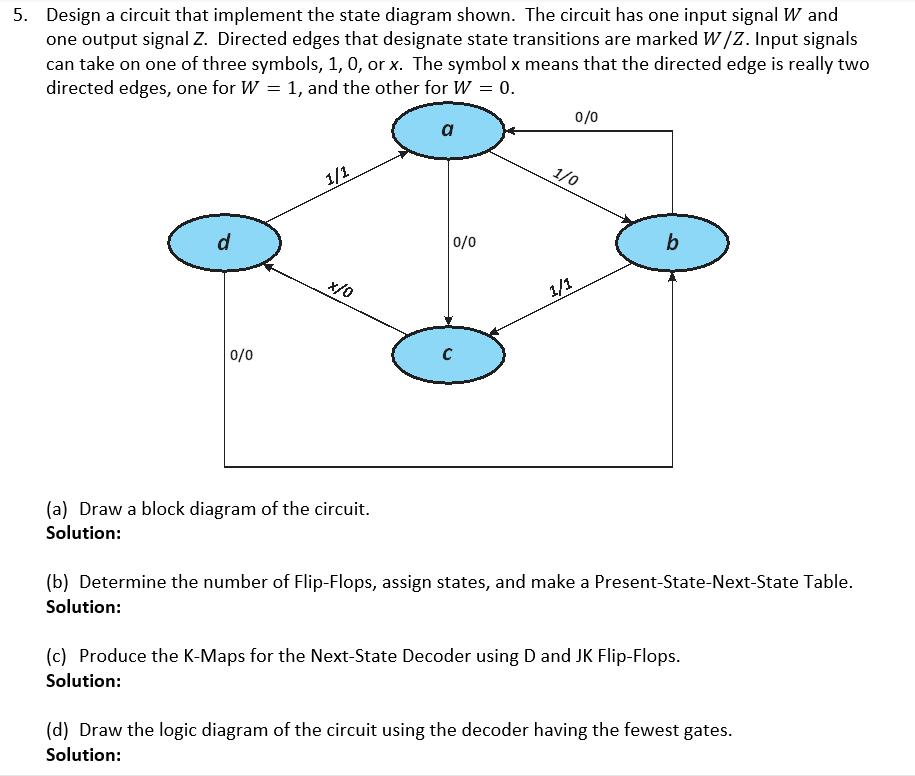
5. Design a circuit that implement the state diagram shown. The circuit has one input signal W and one output signal Z. Directed edges that designate state transitions are marked W/Z. Input signals can take on one of three symbols, 1, 0, or x. The symbol x means that the directed edge is really two directed edges, one for W = 1, and the other for W = 0. d 0/0 1/1 (a) Draw a block diagram of the circuit. Solution: a 0/0 C 0/0 1/0 1/1 (b) Determine the number of Flip-Flops, assign states, and make a Present-State-Next-State Table. Solution: (c) Produce the K-Maps for the Next-State Decoder using D and JK Flip-Flops. Solution: (d) Draw the logic diagram of the circuit using the decoder having the fewest gates. Solution:
Step by Step Solution
3.37 Rating (153 Votes )
There are 3 Steps involved in it

Get step-by-step solutions from verified subject matter experts