

Question: 5. For the switch, LED and buzzer interface shown in Fig. P5: a. Write the port initialization instructions (4 pts.) b. c. Sketch the flow
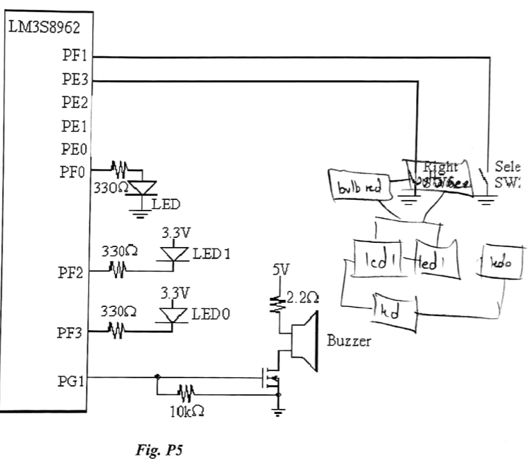
5. For the switch, LED and buzzer interface shown in Fig. P5: a. Write the port initialization instructions (4 pts.) b. c. Sketch the flow chart. (2pts) wnte the complete program for a system that is required to: turn ON the Buzzer and LED 0 & LED 1 when both the switches are pressed simultaneously turn ON LED I when SW6 is pressed turn ON LED 0 when SW2 is pressed tum ON LED in all other scenarios. (6 pts) LM3S8962 PF1 PE2 PE1 PEO PF0 302Z LED 3.3V 330 LED1 5V 3.3V 330 SZLED0 kd Buzzer PG1 Fig. P5 5. For the switch, LED and buzzer interface shown in Fig. P5: a. Write the port initialization instructions (4 pts.) b. c. Sketch the flow chart. (2pts) wnte the complete program for a system that is required to: turn ON the Buzzer and LED 0 & LED 1 when both the switches are pressed simultaneously turn ON LED I when SW6 is pressed turn ON LED 0 when SW2 is pressed tum ON LED in all other scenarios. (6 pts) LM3S8962 PF1 PE2 PE1 PEO PF0 302Z LED 3.3V 330 LED1 5V 3.3V 330 SZLED0 kd Buzzer PG1 Fig. P5
Step by Step Solution
There are 3 Steps involved in it

Get step-by-step solutions from verified subject matter experts