

Question: 5) Problem 3.9 text - sketch the S1, RI, and Q output signals for the NOR SR latch, including the NOT USED cases (use dashed
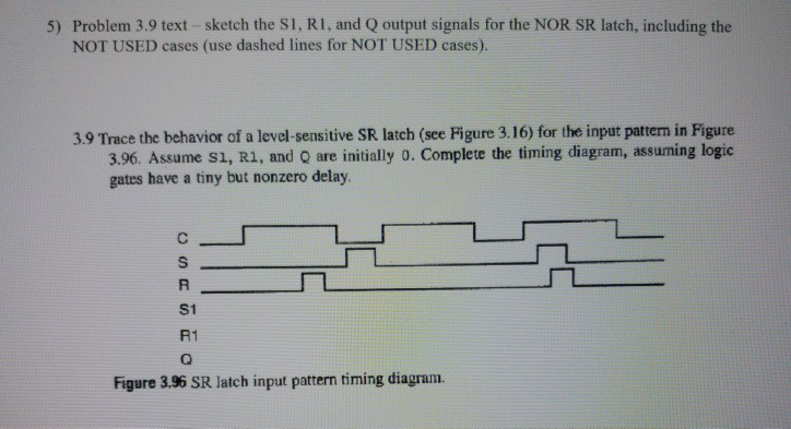
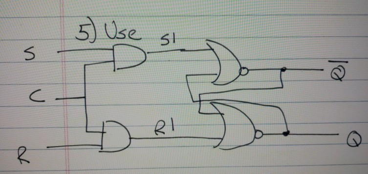
5) Problem 3.9 text - sketch the S1, RI, and Q output signals for the NOR SR latch, including the NOT USED cases (use dashed lines for NOT USED cases) 3.9 Trace the behavior of a level-sensitive SR latch (see Figure 3.16) for the input pattern in Figure 3.96. Assume s1, R1, and O are initially o. Complete the timing diagram, assuming logic gates have a tiny but nonzero delay S1 R1 Figure 3.96 SR latch input patern timing diagram
Step by Step Solution
There are 3 Steps involved in it
1 Expert Approved Answer
Step: 1 Unlock

Question Has Been Solved by an Expert!
Get step-by-step solutions from verified subject matter experts
Step: 2 Unlock
Step: 3 Unlock