

Question: 6 . 1 0 . The beam shown in Fig. P 6 . 1 0 is simply supported with a clear span of 2 6
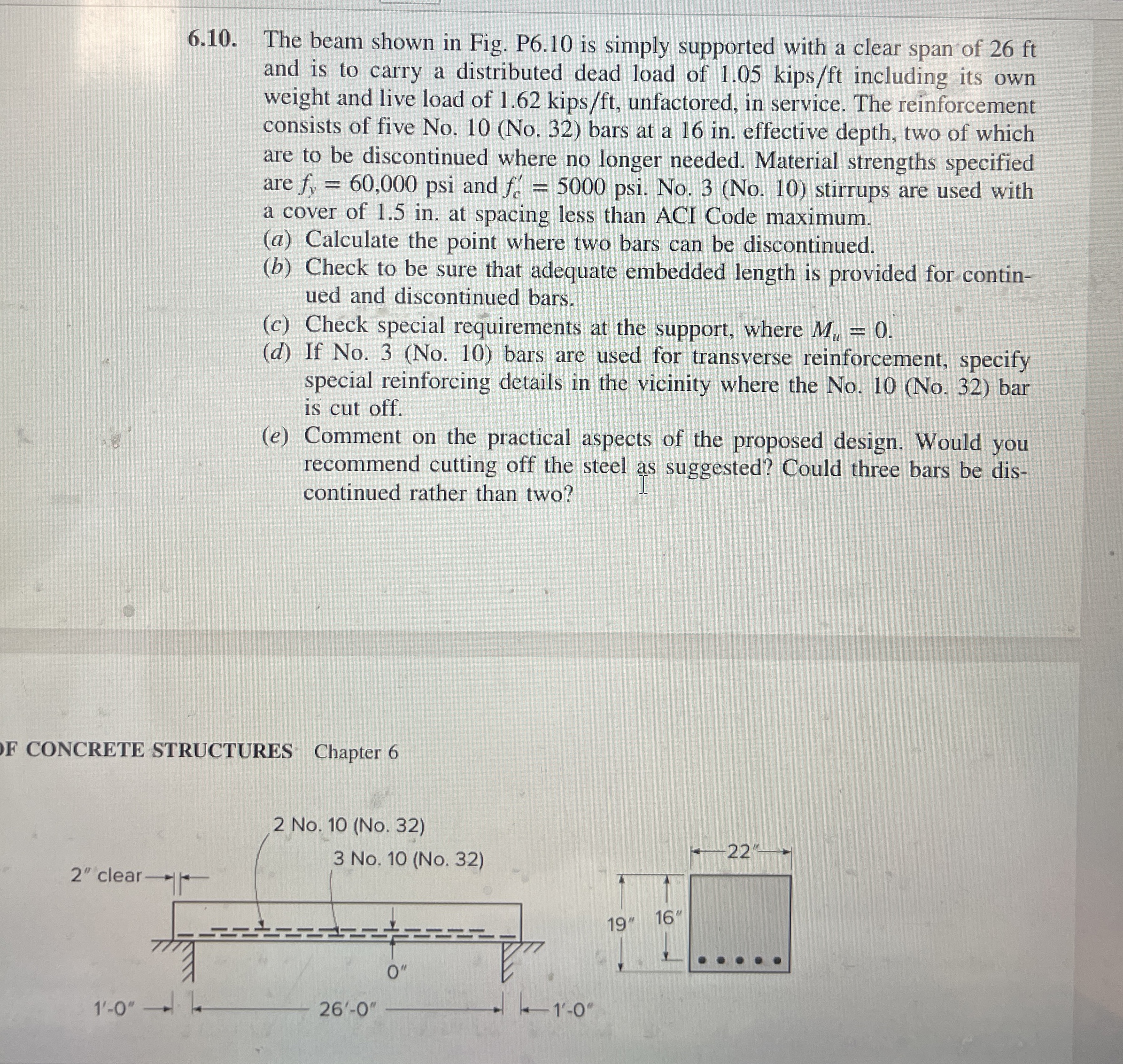
The beam shown in Fig. P is simply supported with a clear span of ft and is to carry a distributed dead load of kip including its own weight and live load of kip unfactored, in service. The reinforcement consists of five NoNo bars at a in effective depth, two of which are to be discontinued where no longer needed. Material strengths specified are psi and psi. NoNo stirrups are used with a cover of in at spacing less than ACI Code maximum.
a Calculate the point where two bars can be discontinued.
b Check to be sure that adequate embedded length is provided for continued and discontinued bars.
c Check special requirements at the support, where
d If NoNo bars are used for transverse reinforcement, specify special reinforcing details in the vicinity where the NoNo bar is cut off.
e Comment on the practical aspects of the proposed design. Would you recommend cutting off the steel as suggested? Could three bars be discontinued rather than two?
F CONCRETE STRUCTURES Chapter
Step by Step Solution
There are 3 Steps involved in it
1 Expert Approved Answer
Step: 1 Unlock

Question Has Been Solved by an Expert!
Get step-by-step solutions from verified subject matter experts
Step: 2 Unlock
Step: 3 Unlock