

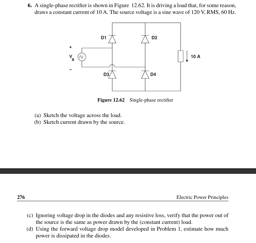
Question: 6 . A single - phase rectifier is shown in Figure 1 2 . 6 2 . It is driving a load that, for some
A singlephase rectifier is shown in Figure It is driving a load that, for some reason, draws a constant current of A The source voltage is a sine wave of mathrm~VmathrmRMSmathrm~Hz
Figure singlepnase recuner
a Sketch the voltage across the load.
b Sketch current drawn by the source.
c Ignoring voltage drop in the diodes and any resistive loss, verify that the power out of the source is the same as power drawn by the constant current load.
d Using the forward voltage drop model developed in Problem estimate how much power is dissipated in the diodes.
Step by Step Solution
There are 3 Steps involved in it
1 Expert Approved Answer
Step: 1 Unlock

Question Has Been Solved by an Expert!
Get step-by-step solutions from verified subject matter experts
Step: 2 Unlock
Step: 3 Unlock