

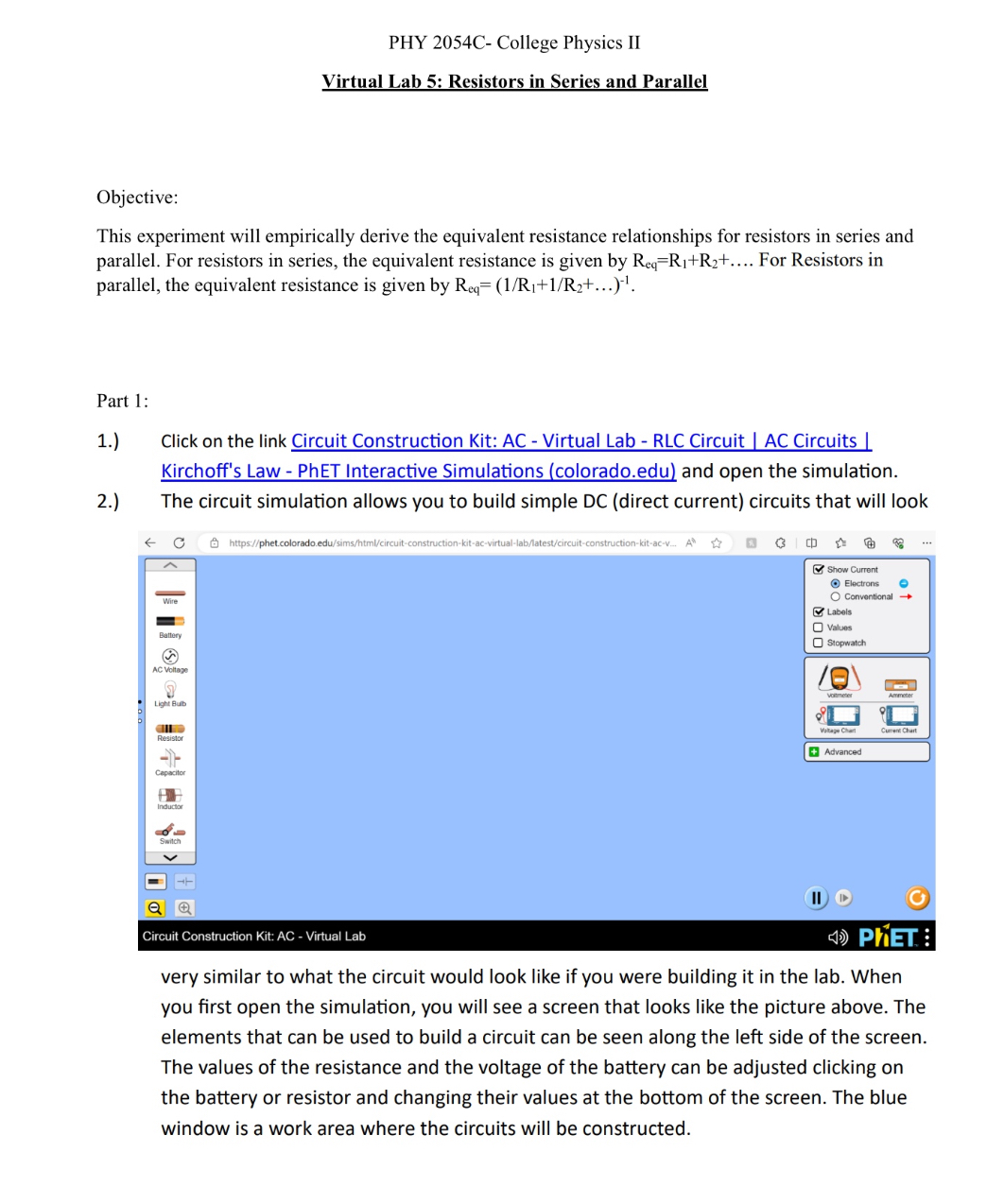
Question: 6.) Close the switch by placing the cursor over the center of the switch and left clicking. Record the voltage and the current in the

![in the table below. Voltage (V) Current (A) s ] 0 e](https://s3.amazonaws.com/si.experts.images/answers/2024/06/667cc2f0d9754_400667cc2f0ab86e.jpg)
![e 2 ] B 00 S 0 = ] o ] 0](https://s3.amazonaws.com/si.experts.images/answers/2024/06/667cc2f16a0d2_401667cc2f13e86f.jpg)


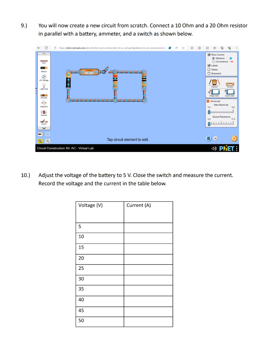
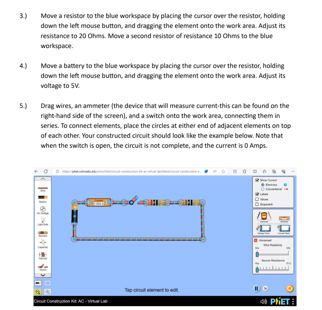
6.) Close the switch by placing the cursor over the center of the switch and left clicking. Record the voltage and the current in the table below. Voltage (V) Current (A) s ] 0 e e 2 ] B 00 S 0 = ] o ] 0 7. Place the cursor over the battery and left click once. You will see a voltage adjuster for the battery at the bottom of the screen. Adjust the voltage to 10.0 V, and again record the voltage and current in the table above. 8.) Continue in this manner until the voltage reaches 50.0 V. Record the voltage and the current in the table above for each trial. PHY 2054C- College Physics II Virtual Lab 5: Resistors in Series and Parallel Objective: This experiment will empirically derive the equivalent resistance relationships for resistors in series and parallel. For resistors in series, the equivalent resistance is given by R,=R;+Ry+.... For Resistors in parallel, the equivalent resistance is given by Reg= (1/Ri+1/Ra+... )" Part 1: 1.) Click on the link Circuit Construction Kit: AC - Virtual Lab - RLC Circuit | AC Circuits Kirchoff's Law - PhET Interactive Simulations (colorado.edu) and open the simulation. 2) The circuit simulation allows you to build simple DC (direct current) circuits that will look ) phet.colorada.edu Q = [ Show Currant Electrons & ; Wire: O Comventional e & Labals Valuas Banry Stopwatch ) AL Vioitage o oLight B 8 AN - Resiston apac: Suckar o = === ol > al & "J s Circuit Construction Kit: AC - Virtual Lab N3 very similar to what the circuit would look like if you were building it in the lab. When you first open the simulation, you will see a screen that looks like the picture above. The elements that can be used to build a circuit can be seen along the left side of the screen. The values of the resistance and the voltage of the battery can be adjusted clicking on the battery or resistor and changing their values at the bottom of the screen. The blue window is a work area where the circuits will be constructed. 9.) You will now create a new circuit from scratch. Connect a 10 Ohm and a 20 Ohm resistor in parallel with a battery, ammeter, and a switch as shown below. - C https//phet.colorado.ed 1-construction-k. Show Current Electrons O Conventional Labels O Values Stopwatch AC Witage LITH BUD voltage Chart. Curent Chat -Advanced Wir Resistivity tiny Source Resistance Tap circuit element to edit. Circuit Construction Kit: AC - Virtual Lab () PHET : 10.) Adjust the voltage of the battery to 5 V. Close the switch and measure the current. Record the voltage and the current in the table below. Voltage (V) Current (A) 5 10 15 20 25 30 35 40 45 50Move a resistor to the blue workspace by placing the cursor over the resistor, holding down the left mouse button, and dragging the element onto the work area. Adjust its resistance to 20 Ohms. Move a second resistor of resistance 10 Ohms to the blue workspace. Move a battery to the blue workspace by placing the cursor over the resistor, holding down the left mouse button, and dragging the element onto the work area. Adjust its voltage to 5V. Drag wires, an ammeter (the device that will measure current-this can be found on the right-hand side of the screen), and a switch onto the work area, connecting them in series. To connect elements, place the circles at either end of adjacent elements on top of each other. Your constructed circuit should look like the example below. Note that when the switch is open, the circuit is not complete, and the current is 0 Amps. C tps//phet.colorado.edu t t & G ( Show Current Electrons e O Conventional 3 Labels [ Values O stopwatch B Advanced Wire Resistivity Io Source Resistance 00 al @ Tap circuit element to edit. "J - J e Circuit Construction Kit: AC - Virtual Lab r{]:}) p'lEr E 11.) 12.) 13.) 14.) Increase the voltage to 10V and measure the current. Record the voltage and the current in the table above. Continue in this manner until a voltage of 50 V is reached. Record the voltage and the current in the table above for each trial. Open an Excel spreadsheet and create a scatter plot for the first data set. Input your current values in the first column and the corresponding voltage values in the second column. Be sure to include proper axis labels, units, and a proper descriptive title. Do a linear fit and find the equation for the best fit line for this graph. What is the slope? What is the equivalent resistance for the two resistors connected in series? What is the theoretical equivalent resistance based on the equation Req=Ri1+R2+....? What is the percent difference between these two values? To calculate the percent difference, take the difference of the two values and divide by the average and then multiply by 100. For your second data set, input your current values in the first column and your voltage values in the second column and construct a scatter plot. Be sure to include proper axis labels, units, and a proper descriptive title. Do a linear fit and obtain the equation for the best fit line. What is the slope? What is the equivalent resistance for the two resistors connected in series? What is the theoretical equivalent resistance based on the equation Req= (1/Ri+1/Ry+...)"'? What is the percent difference between these two values? Analysis: Type up your answers to these questions. Your lab report will consist of these answers, plus the two graphs with descriptions. You may use this document as a template for your report
Step by Step Solution
There are 3 Steps involved in it

Get step-by-step solutions from verified subject matter experts