

Question: 6. Fe-C Phases and Microstructure. 6 pts. Shown below is an enlarged version of the bottom left corner of the Fe-C phase diagram with circles
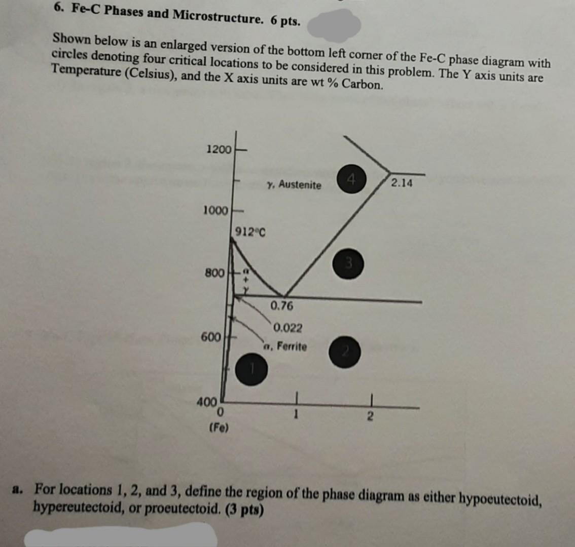
6. Fe-C Phases and Microstructure. 6 pts. Shown below is an enlarged version of the bottom left corner of the Fe-C phase diagram with circles denoting four critical locations to be considered in this problem. The Y axis units are Temperature (Celsius), and the X axis units are wt% Carbon. 1200 4) y, Austenite 2.14 1000 912C 800 0.76 600 0.022 a, Ferrite 400 0 (Fe) a. For locations 1, 2, and 3, define the region of the phase diagram as either hypoeutectoid, hypereutectoid, or proeutectoid. (3 pts) b. Consider cooling a solid of constant composition from location 4 to location 2 through location 3. (3 pts) (i) Draw the starting microstructure of the Austenitic phase at location 4. Label the phase(s). The details do not need to be exact, just approximate. (ii) In region 3, a new phase will form. What is the name of this phase? Where will it form? (iii) In region 2, the austenite will also transform according to a process you have seen before in class. Draw the approximate final microstructure at location 2
Step by Step Solution
There are 3 Steps involved in it

Get step-by-step solutions from verified subject matter experts