

Question: 6. Given a four-bar linkage (Figure 3.7), derive the geometric relationship between the following motion variables of the mechanism. Let the link lengths be
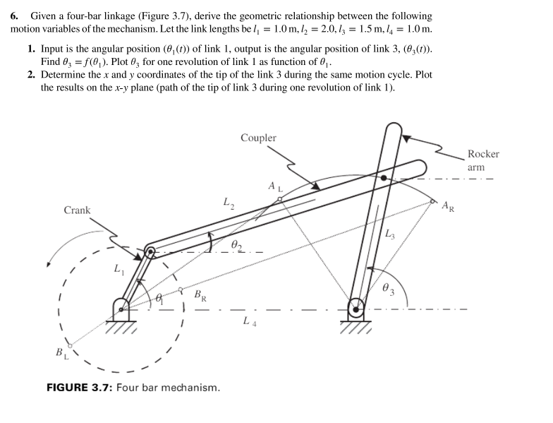
6. Given a four-bar linkage (Figure 3.7), derive the geometric relationship between the following motion variables of the mechanism. Let the link lengths be 1 = 1.0 m, 1 = 2.0, 13 = 1.5 m, 14 = 1.0m. 1. Input is the angular position (8, (t)) of link 1, output is the angular position of link 3, (03(1)). Find 03 = f(0). Plot 03 for one revolution of link 1 as function of 0. 2. Determine the x and y coordinates of the tip of the link 3 during the same motion cycle. Plot the results on the x-y plane (path of the tip of link 3 during one revolution of link 1). Crank L FIGURE 3.7: Four bar mechanism. 4 Coupler 0 L4 AL 43 Ag Rocker arm
Step by Step Solution
There are 3 Steps involved in it
To derive the geometric relationship between the motion variables of the fourbar linkage we can use the law of cosines and trigonometric relationships 1 Input and output angular positions Lets denote the lengths of the four ... View full answer

Get step-by-step solutions from verified subject matter experts