

Question: 7 - 2 4 * The shaft shown in the figure is proposed for the application defined in Problem 3 - 8 3 . The
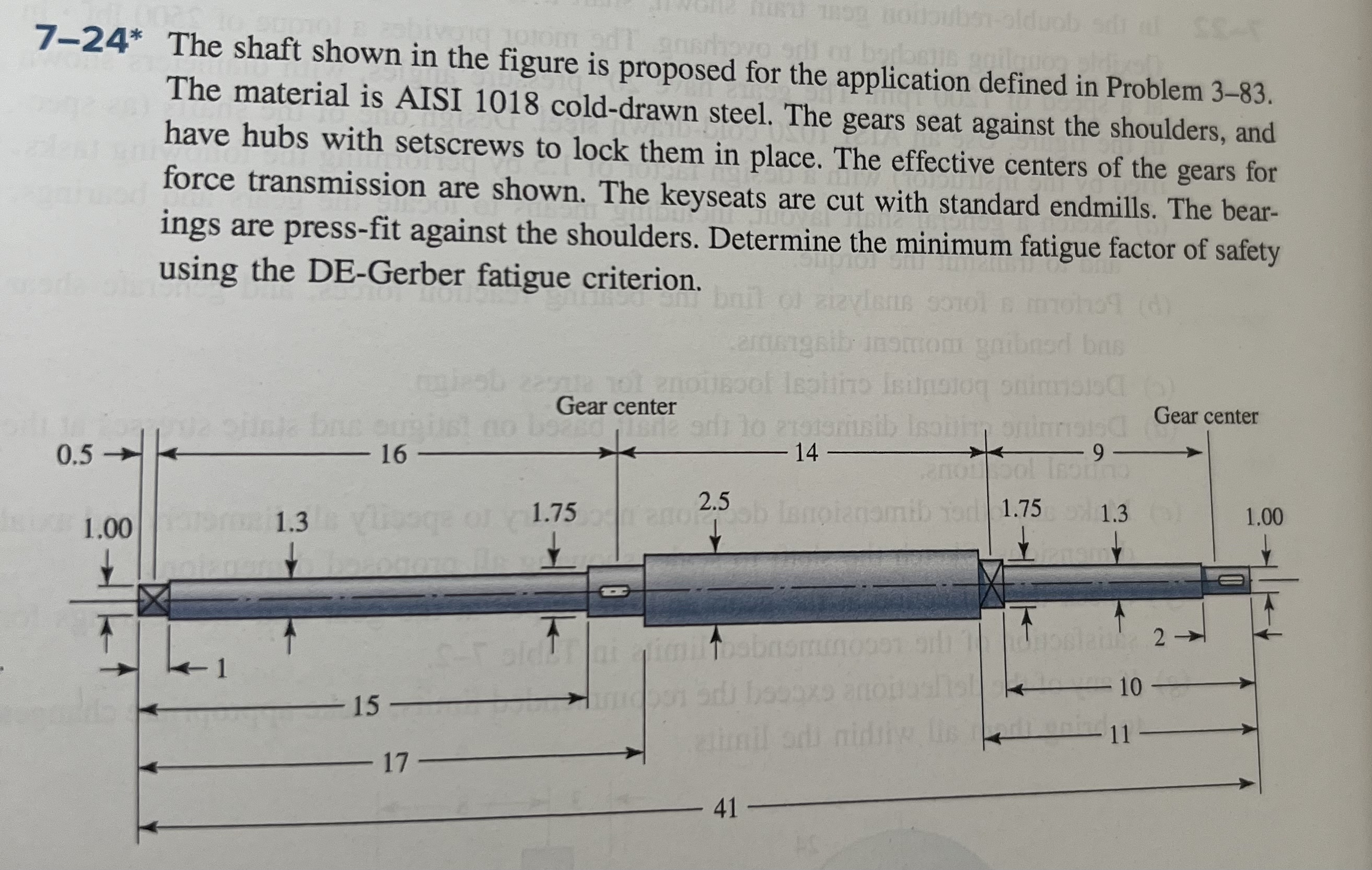
The shaft shown in the figure is proposed for the application defined in Problem The material is AISI colddrawn steel. The gears seat against the shoulders, and have hubs with setscrews to lock them in place. The effective centers of the gears for force transmission are shown. The keyseats are cut with standard endmills. The bearings are pressfit against the shoulders. Determine the minimum fatigue factor of safety using the DEGerber fatigue criterion.
Step by Step Solution
There are 3 Steps involved in it
1 Expert Approved Answer
Step: 1 Unlock

Question Has Been Solved by an Expert!
Get step-by-step solutions from verified subject matter experts
Step: 2 Unlock
Step: 3 Unlock