

Question: 7 . A spring - loaded relief valve is shown in Fig. It consists of a plunger, which is mounted in the main body covering
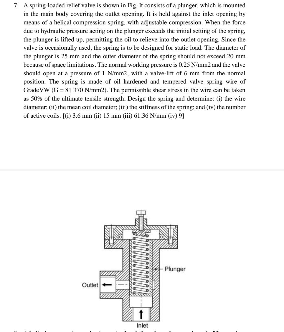
A springloaded relief valve is shown in Fig. It consists of a plunger, which is mounted in the main body covering the outlet opening. It is held against the inlet opening by means of a helical compression spring, with adjustable compression. When the force due to hydraulic pressure acting on the plunger exceeds the initial setting of the spring, the plunger is lifted up permitting the oil to relieve into the outlet opening. Since the valve is occasionally used, the spring is to be designed for static load. The diameter of the plunger is mm and the outer diameter of the spring should not exceed mm because of space limitations The normal working pressure is mathrm~Nmathrmmm and the valve should open at a pressure of mathrm~Nmathrmmm with a valvelift of mm from the normal position. The spring is made of oil hardened and tempered valve spring wire of GradeVW mathrmGmathrm~Nmathrmmm The permissible shear stress in the wire can be taken as of the ultimate tensile strength. Design the spring and determine: i the wire diameter; ii the mean coil diameter; iii the stiffness of the spring; and iv the number of active coils. i mm ii mm iiimathrm~Nmathrmmmiv
Step by Step Solution
There are 3 Steps involved in it
1 Expert Approved Answer
Step: 1 Unlock

Question Has Been Solved by an Expert!
Get step-by-step solutions from verified subject matter experts
Step: 2 Unlock
Step: 3 Unlock