

Question: 7. Below are the design parameters for a concrete bridge. Calculate the maximum designed bearing capacity/load per pile (in tons after dividing by the given
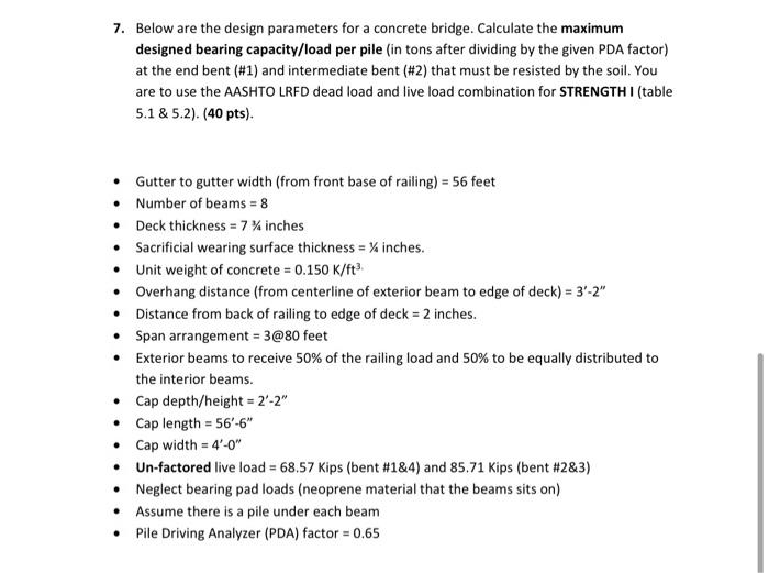
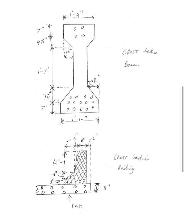
7. Below are the design parameters for a concrete bridge. Calculate the maximum designed bearing capacity/load per pile (in tons after dividing by the given PDA factor) at the end bent (#1) and intermediate bent (#2) that must be resisted by the soil. You are to use the AASHTO LRFD dead load and live load combination for STRENGTH I (table 5.1 & 5.2). (40 pts). Gutter to gutter width (from front base of railing) = 56 feet Number of beams = 8 Deck thickness = 7 % inches Sacrificial wearing surface thickness = % inches. Unit weight of concrete = 0.150 K/ft? Overhang distance (from centerline of exterior beam to edge of deck) = 3'-2" Distance from back of railing to edge of deck = 2 inches. Span arrangement = 3@80 feet Exterior beams to receive 50% of the railing load and 50% to be equally distributed to the interior beams. Cap depth/height = 2-2" Cap length = 56'-6" Cap width = 4'-0" Un-factored live load = 68.57 Kips (bent #184) and 85.71 Kips (bent #2&3) Neglect bearing pad loads (neoprene material that the beams sits on) Assume there is a pile under each beam Pile Driving Analyzer (PDA) factor = 0.65 1 Cross Section Beam 18th 7 OO 0 D 0000 O Cross Section Railing mo o 0 log 0 o 8" e n ( Deck
Step by Step Solution
There are 3 Steps involved in it

Get step-by-step solutions from verified subject matter experts