

Question: 7 DESIGN A TWO - SPEED ACTUATOR CIRCUIT Procedure Overview In this procedure, you will design a circuit to provide two speeds to an actuator
DESIGN A TWOSPEED ACTUATOR CIRCUIT
Procedure Overview
In this procedure, you will design a circuit to provide two speeds to an actuator as it operates in one direction.
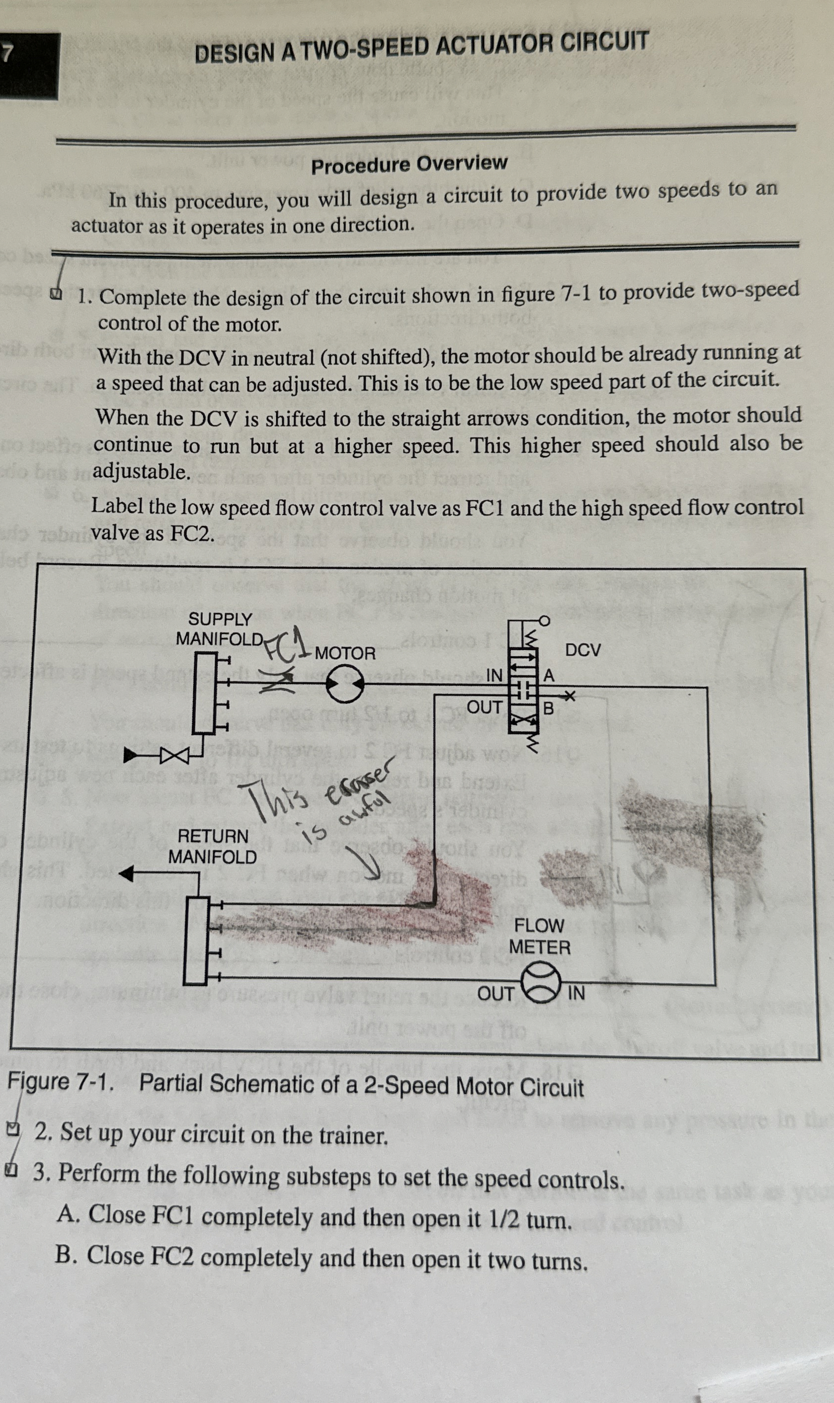
Complete the design of the circuit shown in figure to provide twospeed control of the motor.
With the DCV in neutral not shifted the motor should be already running at a speed that can be adjusted. This is to be the low speed part of the circuit. When the DCV is shifted to the straight arrows condition, the motor should continue to run but at a higher speed. This higher speed should also be adjustable.
Label the low speed flow control valve as and the high speed flow control valve as FC
Figure Partial Schematic of a Speed Motor Circuit
Set up your circuit on the trainer.
Perform the following substeps to set the speed controls.
A Close FC completely and then open it turn.
B Close FC completely and then open it two turns.
Step by Step Solution
There are 3 Steps involved in it
1 Expert Approved Answer
Step: 1 Unlock

Question Has Been Solved by an Expert!
Get step-by-step solutions from verified subject matter experts
Step: 2 Unlock
Step: 3 Unlock