

Question: A 1 6 foot long beam supports the loading shown; the cross section is shown on the next page. Points ( mathbf {
A foot long beam supports the loading shown; the cross section is shown on the next page.
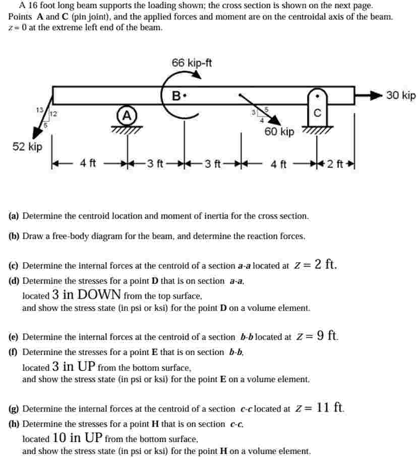
Points mathbfA and mathbfCpin joint and the applied forces and moment are on the centroidal axis of the beam. z at the extreme left end of the beam.
a Determine the centroid location and moment of inertia for the cross section.
b Draw a freebody diagram for the beam, and determine the reaction forces.
c Determine the internal forces at the centroid of a section aa located at Zmathrmft
d Determine the stresses for a point D that is on section aa located in DOWN from the top surface. and show the stress state in psi or ksi for the point mathbfD on a volume element.
e Determine the internal forces at the centroid of a section bb located at Zmathrmft
f Determine the stresses for a point E that is on section boldsymbolbboldsymbolb located in UP from the bottom surface, and show the stress state in psi or ksi for the point mathbfE on a volume element.
g Determine the internal forces at the centroid of a section cclocated at Zmathrmft
h Determine the stresses for a point mathbfH that is on section boldsymbolcc located in UP from the bottom surface. and show the stress state in psi or ksi for the point mathbfH on a volume element.
Step by Step Solution
There are 3 Steps involved in it
1 Expert Approved Answer
Step: 1 Unlock

Question Has Been Solved by an Expert!
Get step-by-step solutions from verified subject matter experts
Step: 2 Unlock
Step: 3 Unlock