

Question: a 2. The gravity draining tank in Figure 2 has a linear valve (i.e., F;=K,P) and the outlet flow can be considered to follow square
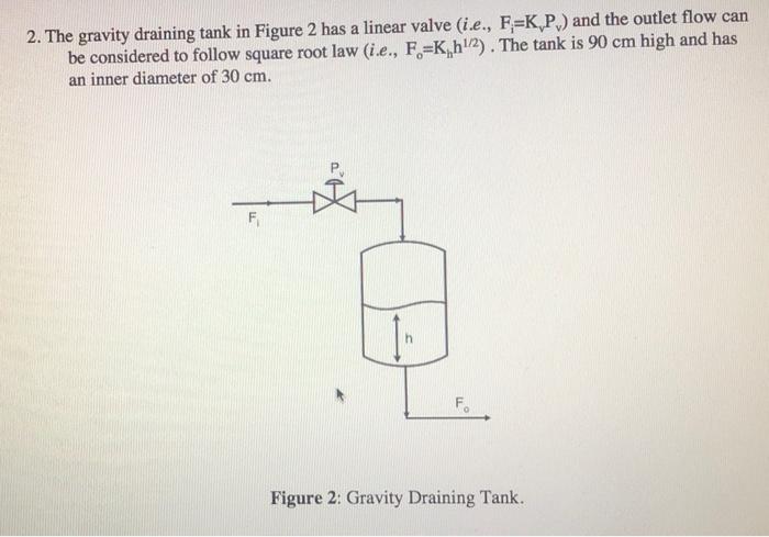
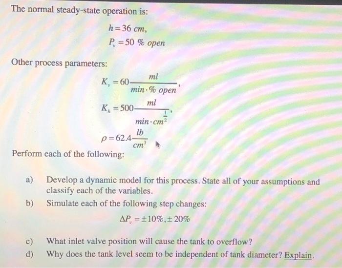
a 2. The gravity draining tank in Figure 2 has a linear valve (i.e., F;=K,P) and the outlet flow can be considered to follow square root law (i.e., F.=K, 112). The tank is 90 cm high and has an inner diameter of 30 cm. F F Figure 2: Gravity Draining Tank. The normal steady-state operation is: h = 36 cm P. = 50 % open Other process parameters: ml K = 60 min. % open ml R = 500- min.cm2 lb p=62.4 cm Perform each of the following: a) b) Develop a dynamic model for this process. State all of your assumptions and classify each of the variables. Simulate each of the following step changes: AP = $10%, 20% c) d) What inlet valve position will cause the tank to overflow? Why does the tank level seem to be independent of tank diameter? Explain
Step by Step Solution
There are 3 Steps involved in it

Get step-by-step solutions from verified subject matter experts