

Question: A 4-bit Johnson counter advances on positive clock edges and generates outputs in the sequence shown in the table below. Draw the assigned state table
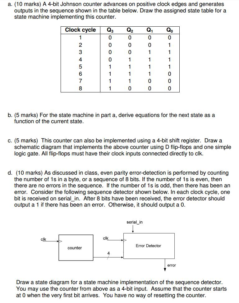
A 4-bit Johnson counter advances on positive clock edges and generates outputs in the sequence shown in the table below. Draw the assigned state table for a state machine implementing this counter. For the state machine in part a, derive equations for the next state as a function of the current state. This counter can also be implemented using a 4-bit shift register. Draw a schematic diagram that implements the above counter using D flip-flops and one simple logic gate. All flip-flops must have their clock inputs connected directly to clk. As discussed in class, even parity error-detection is performed by counting the number of 1s in a byte, or a sequence of 8 bits. If the number of 1s is even, then there are no errors in the sequence. If the number of 1s is odd, then there has been an error. Consider the following sequence detector shown below. In each clock cycle, one bit is received on serial_in. After 8 bits have been received, the error detector should output a 1 if there has been an error. Otherwise, it should output a 0. Draw a state diagram for a state machine implementation of the sequence detector. You may use the counter from above as a 4-bit input. Assume that the counter starts at 0 when the very first bit arrives. You have no way of resetting the counter
Step by Step Solution
There are 3 Steps involved in it

Get step-by-step solutions from verified subject matter experts